Set Selection Screen for Allotting ID Numbers to Multiple Screens/Each Set
This sets the VIDEO WALL NO. and SET ID NO.
ID Selection Screen
Press the EXIT button twice.
Press the EXIT button once to return to the main menu. To delete the main menu, press the button once more.
1.Press the ID SELECT button of the remote control This displays the ID selection screen.
ID SELECT
*Selects the ID number for each monitor in a Multiple screen so that each monitor can be adjusted with the remote control one at a time.
*Only monitors that have been set with the appropriate ID number can be controlled.
Note: The ID select button is valid regardless of the ID set for each monitor.
*This function is also valid when this monitor is controlled via the RS232 connector.
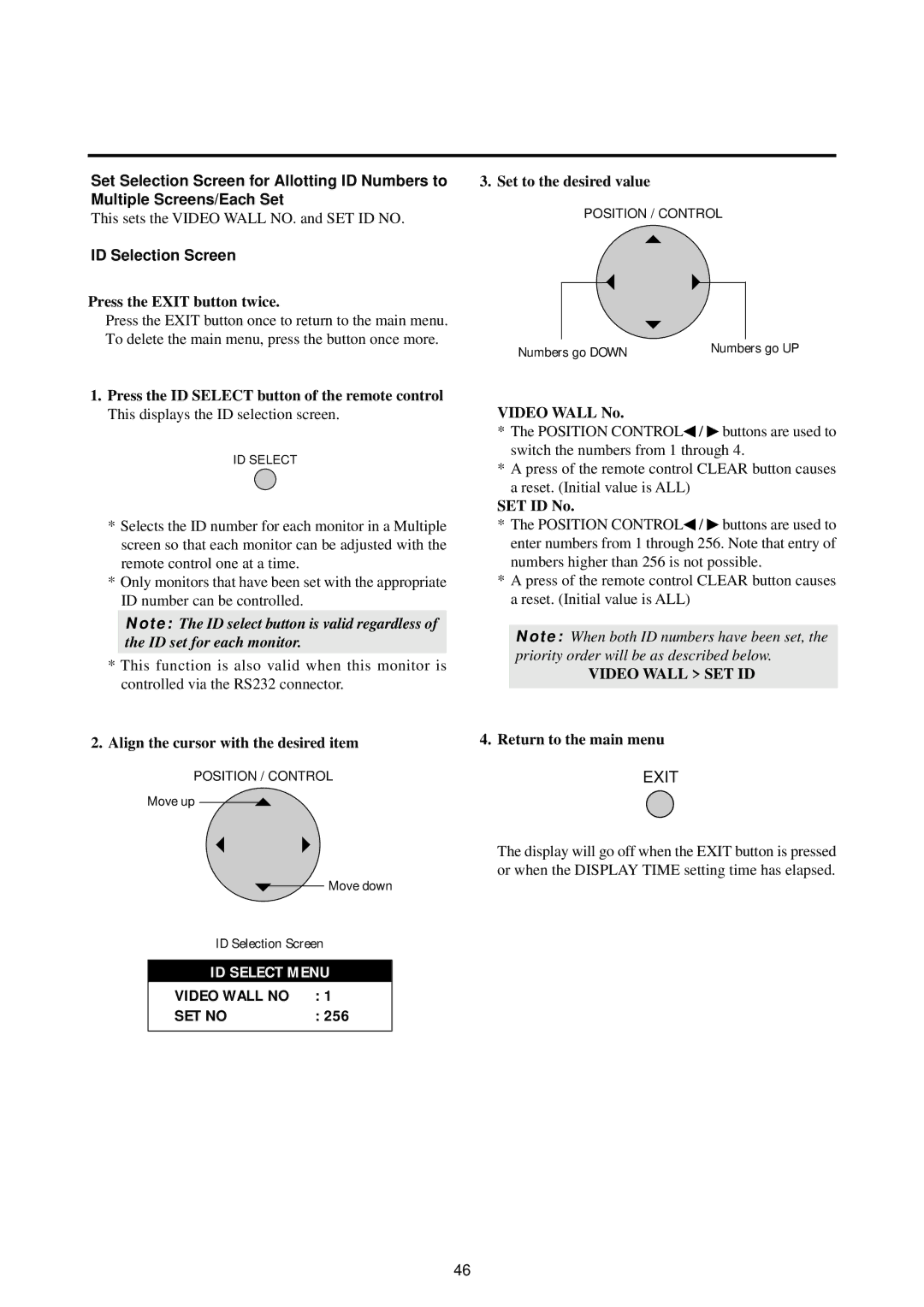
2.Align the cursor with the desired item
POSITION / CONTROL
Move up
Move down
ID Selection Screen
ID SELECT MENU
VIDEO WALL NO | : 1 |
SET NO | : 256 |
3. Set to the desired value
POSITION / CONTROL
Numbers go DOWN | Numbers go UP |
VIDEO WALL No.
*The POSITION CONTROL◀ / ♣ buttons are used to switch the numbers from 1 through 4.
*A press of the remote control CLEAR button causes a reset. (Initial value is ALL)
SET ID No.
*The POSITION CONTROL◀ / ♣ buttons are used to enter numbers from 1 through 256. Note that entry of numbers higher than 256 is not possible.
*A press of the remote control CLEAR button causes a reset. (Initial value is ALL)
Note: When both ID numbers have been set, the priority order will be as described below.
VIDEO WALL > SET ID
4.Return to the main menu
EXIT
The display will go off when the EXIT button is pressed or when the DISPLAY TIME setting time has elapsed.
46