i2022 ISDN Teleset
Pin
Interface
Pin
Interface
IN OUT
Power
Adapter
AC 120V
Pin
Interface
Pin
Interface
Pin
| AUX |
| |
Lucent | |||
i2022 | |||
|
|
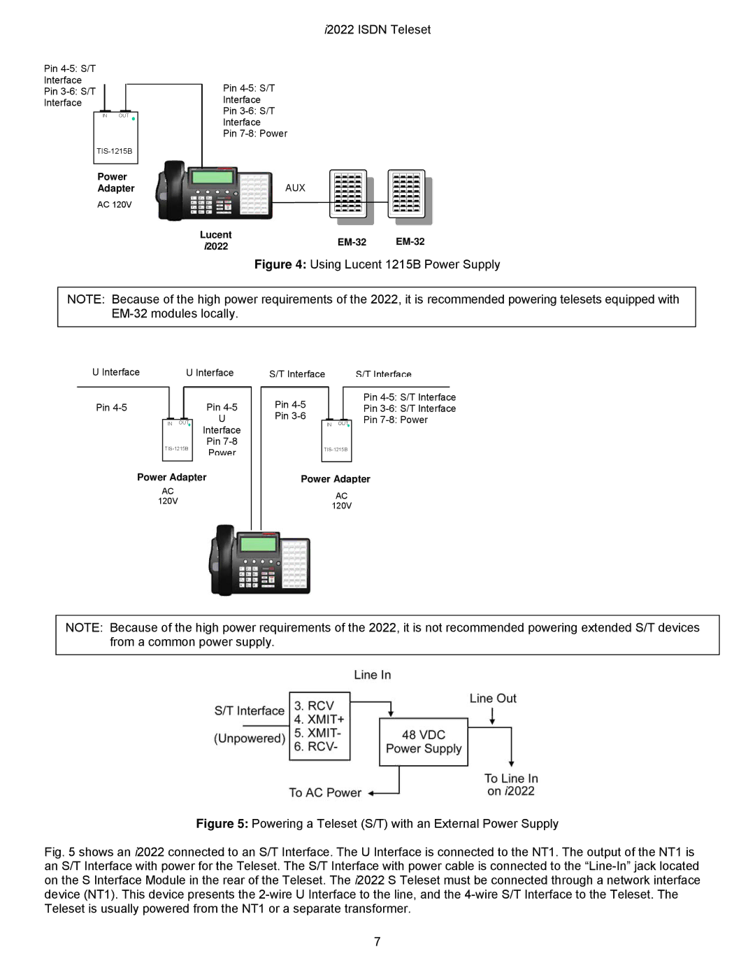
Figure 4: Using Lucent 1215B Power Supply
NOTE: Because of the high power requirements of the 2022, it is recommended powering telesets equipped with
U Interface |
| U Interface | ||||
|
|
|
|
|
|
|
Pin |
|
|
| Pin | ||
|
|
|
|
|
| U |
|
| IN | OUT | Interface | ||
|
|
|
|
|
| |
| Pin | |||||
| Power | |||||
|
|
|
|
|
| |
Power Adapter | ||||||
AC |
|
|
| |||
120V |
|
|
| |||
|
|
|
|
|
|
|
S/T Interface | S/T Interface | ||||||||
|
|
|
|
|
|
|
|
|
|
Pin |
|
|
|
|
| Pin | |||
|
|
|
|
| Pin | ||||
Pin |
|
|
|
|
|
| |||
|
|
|
|
|
| Pin | |||
|
| IN OUT | |||||||
|
|
| |||||||
|
|
|
|
|
|
|
|
|
|
Power Adapter
AC
120V
NOTE: Because of the high power requirements of the 2022, it is not recommended powering extended S/T devices from a common power supply.
Figure 5: Powering a Teleset (S/T) with an External Power Supply
Fig. 5 shows an i2022 connected to an S/T Interface. The U Interface is connected to the NT1. The output of the NT1 is an S/T Interface with power for the Teleset. The S/T Interface with power cable is connected to the “Line-In” jack located on the S Interface Module in the rear of the Teleset. The i2022 S Teleset must be connected through a network interface device (NT1). This device presents the 2-wire U Interface to the line, and the 4-wire S/T Interface to the Teleset. The Teleset is usually powered from the NT1 or a separate transformer.
7
