PART 2
HARDWARE
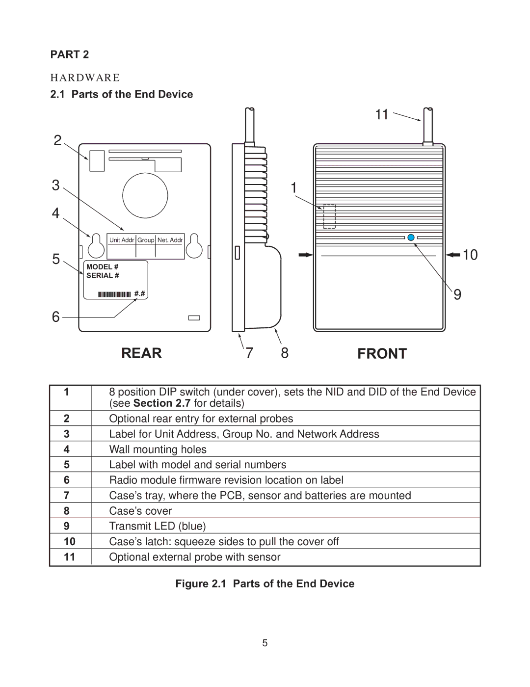
2.1 Parts of the End Device
2 |
|
3 |
|
4 |
|
5 | Unit Addr Group Net. Addr |
MODEL # | |
| SERIAL # |
6 | #.# |
|
REAR
| 1 |
7 | 8 |
11 |
10 |
9 |
FRONT |
18 position DIP switch (under cover), sets the NID and DID of the End Device (see Section 2.7 for details)
2Optional rear entry for external probes
3Label for Unit Address, Group No. and Network Address
4Wall mounting holes
5Label with model and serial numbers
6Radio module firmware revision location on label
7Case’s tray, where the PCB, sensor and batteries are mounted
8Case’s cover
9Transmit LED (blue)
10Case’s latch: squeeze sides to pull the cover off
11Optional external probe with sensor
Figure 2.1 Parts of the End Device
5