2.7.2 DIP Switch Setup: Network ID (NID)
Each sensor network has a unique Network ID (or NID).
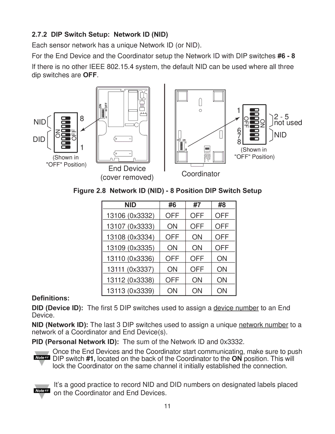
For the End Device and the Coordinator setup the Network ID with DIP switches #6 - 8 If there is no other IEEE 802.15.4 system, the default NID can be used where all three dip switches are OFF.
|
|
| ON OFF |
|
| 1 |
| 2 - 5 |
NID |
| 8 | 8 |
|
|
| ||
| 1 |
|
| OFF | ||||
|
|
|
| 6 | ON not used | |||
DID |
|
|
|
|
|
| NID | |
ON OFF | 1 |
| OFF ON1 |
| 7 |
| ||
|
| 8 | 1 2 3 4 | 8(Shown in | ||||
| (Shown in |
| End Device |
| SERIAL DEFAULT DHCP TERMINAL | "OFF" Position) | ||
| "OFF" Position) | Coordinator |
|
| ||||
|
|
| (cover removed) |
|
| |||
| Figure 2.8 Network ID (NID) - 8 Position DIP Switch Setup | |||||||
|
|
| NID | #6 | #7 | #8 |
|
|
|
|
| 13106 (0x3332) | OFF | OFF | OFF |
|
|
|
|
| 13107 (0x3333) | ON | OFF | OFF |
|
|
|
|
| 13108 (0x3334) | OFF | ON | OFF |
|
|
|
|
| 13109 (0x3335) | ON | ON | OFF |
|
|
|
|
| 13110 (0x3336) | OFF | OFF | ON |
|
|
|
|
| 13111 (0x3337) | ON | OFF | ON |
|
|
|
|
| 13112 (0x3338) | OFF | ON | ON |
|
|
Definitions: |
| 13113 (0x3339) | ON | ON | ON |
|
| |
DID (Device ID): The first 5 DIP switches used to assign a device number to an End Device.
NID (Network ID): The last 3 DIP switches used to assign a unique network number to a network of a Coordinator and End Device(s).
PID (Personal Network ID): The sum of the Network ID and 0x3332.
Once the End Devices and the Coordinator start communicating, make sure to push DIP switch #1, located on the back of the Coordinator to the ON position. This will lock the Coordinator on the same channel it initially established the connection.
It’s a good practice to record NID and DID numbers on designated labels placed ![]() on the Coordinator and End Devices.
on the Coordinator and End Devices.
11