2.5 Parts of the Coordinator (continued)
17 Diagnostics LED: (Yellow and Green) Diagnostics: at
DHCP: if DHCP is enabled, they blink and stay solid periodically
Network Link LED: (Green) Solid: Indicates good network link.
Activity LED: (Red) Blinking: Indicates network activities (receiving or sending packets).
18 Receive LED (blue) while blinking, the Coordinator looks for the clearest channel to communicate. Once it finds that channel, the light will change to solid.
19 Antenna connector
20 Power LED: (Green) Solid: Indicates
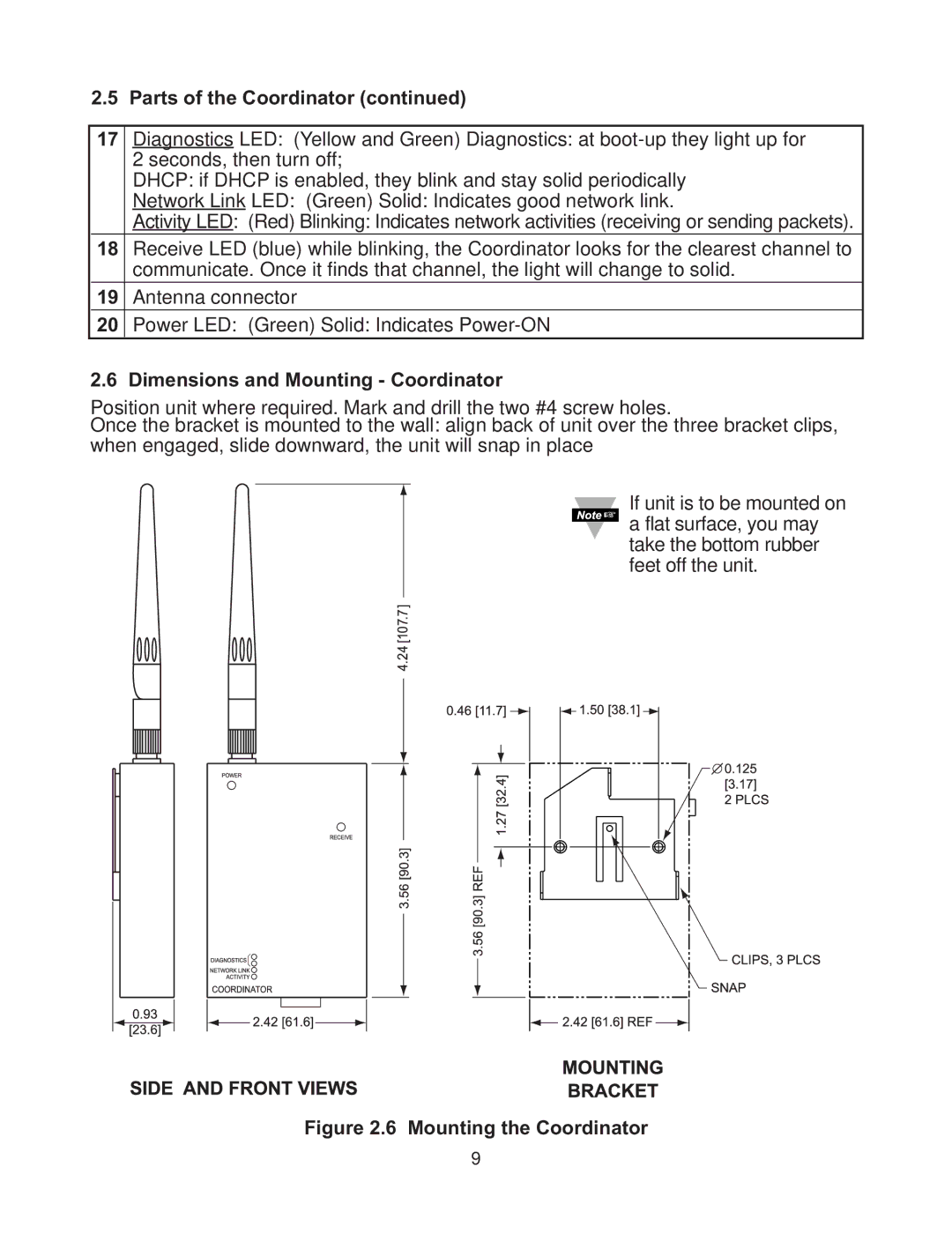
2.6 Dimensions and Mounting - Coordinator
Position unit where required. Mark and drill the two #4 screw holes.
Once the bracket is mounted to the wall: align back of unit over the three bracket clips, when engaged, slide downward, the unit will snap in place
If unit is to be mounted on a flat surface, you may take the bottom rubber feet off the unit.
Figure 2.6 Mounting the Coordinator
9