CHILLER FAMILIARIZATION
(Fig. 1, 2A, and 2B)
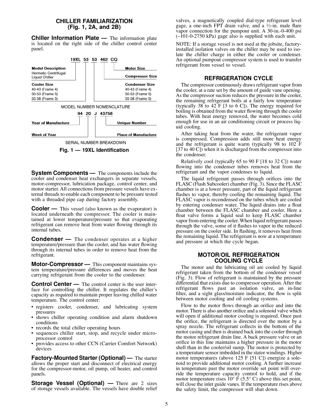
Chiller Information Plate Ð The information plate is located on the right side of the chiller control center panel.
Fig. 1 Ð 19XL Identi®cation
System Components Ð The components include the cooler and condenser heat exchangers in separate vessels, motor-compressor, lubrication package, control center, and motor starter. All connections from pressure vessels have ex- ternal threads to enable each component to be pressure tested with a threaded pipe cap during factory assembly.
Cooler Ð This vessel (also known as the evaporator) is located underneath the compressor. The cooler is main- tained at lower temperature/pressure so that evaporating refrigerant can remove heat from water ¯owing through its internal tubes.
Condenser Ð The condenser operates at a higher temperature/pressure than the cooler, and has water ¯owing through its internal tubes in order to remove heat from the refrigerant.
Motor-Compressor Ð This component maintains sys- tem temperature/pressure differences and moves the heat carrying refrigerant from the cooler to the condenser.
Control Center Ð The control center is the user inter- face for controlling the chiller. It regulates the chiller's capacity as required to maintain proper leaving chilled water temperature. The control center:
·registers cooler, condenser, and lubricating system pressures
·shows chiller operating condition and alarm shutdown conditions
·records the total chiller operating hours
·sequences chiller start, stop, and recycle under micro- processor control
·provides access to other CCN (Carrier Comfort Network) devices
Factory-Mounted Starter (Optional) Ð The starter allows the proper start and disconnect of electrical energy for the compressor-motor, oil pump, oil heater, and control panels.
Storage Vessel (Optional) Ð There are 2 sizes of storage vessels available. The vessels have double relief
valves, a magnetically coupled dial-type refrigerant level gage, a one-inch FPT drain valve, and a 1¤2-in. male ¯are vapor connection for the pumpout unit. A 30-in.-0-400 psi (±101-0-2750 kPa) gage also is supplied with each unit.
NOTE: If a storage vessel is not used at the jobsite, factory- installed isolation valves on the chiller may be used to iso- late the chiller charge in either the cooler or condenser. An optional pumpout compressor system is used to transfer refrigerant from vessel to vessel.
REFRIGERATION CYCLE
The compressor continuously draws refrigerant vapor from the cooler, at a rate set by the amount of guide vane opening. As the compressor suction reduces the pressure in the cooler, the remaining refrigerant boils at a fairly low temperature (typically 38 to 42 F [3 to 6 C]). The energy required for boiling is obtained from the water ¯owing through the cooler tubes. With heat energy removed, the water becomes cold enough for use in an air conditioning circuit or process liq- uid cooling.
After taking heat from the water, the refrigerant vapor is compressed. Compression adds still more heat energy and the refrigerant is quite warm (typically 98 to 102 F [37 to 40 C]) when it is discharged from the compressor into the condenser.
Relatively cool (typically 65 to 90 F [18 to 32 C]) water ¯owing into the condenser tubes removes heat from the refrigerant and the vapor condenses to liquid.
The liquid refrigerant passes through ori®ces into the FLASC (Flash Subcooler) chamber (Fig. 3). Since the FLASC chamber is at a lower pressure, part of the liquid refrigerant ¯ashes to vapor, thereby cooling the remaining liquid. The FLASC vapor is recondensed on the tubes which are cooled by entering condenser water. The liquid drains into a ¯oat chamber between the FLASC chamber and cooler. Here a ¯oat valve forms a liquid seal to keep FLASC chamber vapor from entering the cooler. When liquid refrigerant passes through the valve, some of it ¯ashes to vapor in the reduced pressure on the cooler side. In ¯ashing, it removes heat from the remaining liquid. The refrigerant is now at a temperature and pressure at which the cycle began.
MOTOR/OIL REFRIGERATION
COOLING CYCLE
The motor and the lubricating oil are cooled by liquid refrigerant taken from the bottom of the condenser vessel (Fig. 3). Flow of refrigerant is maintained by the pressure differential that exists due to compressor operation. After the refrigerant ¯ows past an isolation valve, an in-line ®lter, and a sight glass/moisture indicator, the ¯ow is split between motor cooling and oil cooling systems.
Flow to the motor ¯ows through an ori®ce and into the motor. There is also another ori®ce and a solenoid valve which will open if additional motor cooling is required. Once past the ori®ce, the refrigerant is directed over the motor by a spray nozzle. The refrigerant collects in the bottom of the motor casing and then is drained back into the cooler through the motor refrigerant drain line. A back pressure valve or an ori®ce in this line maintains a higher pressure in the motor shell than in the cooler/oil sump. The motor is protected by a temperature sensor imbedded in the stator windings. Higher motor temperatures (above 125 F [51 C]) energize a sole- noid to provide additional motor cooling. A further increase in temperature past the motor override set point will over- ride the temperature capacity control to hold, and if the motor temperature rises 10° F (5.5° C) above this set point, will close the inlet guide vanes. If the temperature rises above the safety limit, the compressor will shut down.