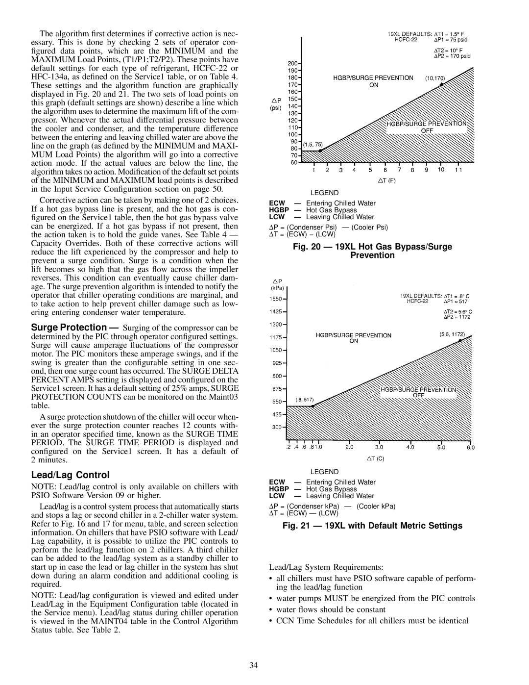
The algorithm ®rst determines if corrective action is nec- essary. This is done by checking 2 sets of operator con- ®gured data points, which are the MINIMUM and the MAXIMUM Load Points, (T1/P1;T2/P2). These points have default settings for each type of refrigerant, HCFC-22 or HFC-134a, as de®ned on the Service1 table, or on Table 4. These settings and the algorithm function are graphically displayed in Fig. 20 and 21. The two sets of load points on this graph (default settings are shown) describe a line which the algorithm uses to determine the maximum lift of the com- pressor. Whenever the actual differential pressure between the cooler and condenser, and the temperature difference between the entering and leaving chilled water are above the line on the graph (as de®ned by the MINIMUM and MAXI- MUM Load Points) the algorithm will go into a corrective action mode. If the actual values are below the line, the algorithm takes no action. Modi®cation of the default set points of the MINIMUM and MAXIMUM load points is described in the Input Service Con®guration section on page 50.

Corrective action can be taken by making one of 2 choices. If a hot gas bypass line is present, and the hot gas is con- ®gured on the Service1 table, then the hot gas bypass valve can be energized. If a hot gas bypass if not present, then the action taken is to hold the guide vanes. See Table 4 Ð Capacity Overrides. Both of these corrective actions will reduce the lift experienced by the compressor and help to prevent a surge condition. Surge is a condition when the lift becomes so high that the gas ¯ow across the impeller reverses. This condition can eventually cause chiller dam- age. The surge prevention algorithm is intended to notify the operator that chiller operating conditions are marginal, and to take action to help prevent chiller damage such as low- ering entering condenser water temperature.

Surge Protection Ð Surging of the compressor can be determined by the PIC through operator con®gured settings. Surge will cause amperage ¯uctuations of the compressor motor. The PIC monitors these amperage swings, and if the swing is greater than the con®gurable setting in one sec- ond, then one surge count has occurred. The SURGE DELTA PERCENT AMPS setting is displayed and con®gured on the Service1 screen. It has a default setting of 25% amps, SURGE PROTECTION COUNTS can be monitored on the Maint03 table.

A surge protection shutdown of the chiller will occur when- ever the surge protection counter reaches 12 counts with- in an operator speci®ed time, known as the SURGE TIME PERIOD. The SURGE TIME PERIOD is displayed and con®gured on the Service1 screen. It has a default of 2 minutes.

Lead/Lag Control

NOTE: Lead/lag control is only available on chillers with PSIO Software Version 09 or higher.

Lead/lag is a control system process that automatically starts and stops a lag or second chiller in a 2-chiller water system. Refer to Fig. 16 and 17 for menu, table, and screen selection information. On chillers that have PSIO software with Lead/ Lag capability, it is possible to utilize the PIC controls to perform the lead/lag function on 2 chillers. A third chiller can be added to the lead/lag system as a standby chiller to start up in case the lead or lag chiller in the system has shut down during an alarm condition and additional cooling is required.

NOTE: Lead/lag con®guration is viewed and edited under Lead/Lag in the Equipment Con®guration table (located in the Service menu). Lead/lag status during chiller operation is viewed in the MAINT04 table in the Control Algorithm Status table. See Table 2.


LEGEND

ECW

Ð Entering Chilled Water

HGBP

Ð Hot Gas Bypass

LCW

Ð Leaving Chilled Water

DP = (Condenser Psi) Ð (Cooler Psi)

DT = (ECW) − (LCW)

Fig. 20 Ð 19XL Hot Gas Bypass/Surge

Prevention


LEGEND

ECW

Ð Entering Chilled Water

HGBP

Ð Hot Gas Bypass

LCW

Ð Leaving Chilled Water

DP = (Condenser kPa) Ð (Cooler kPa)

DT = (ECW) Ð (LCW)

Fig. 21 Ð 19XL with Default Metric Settings

Lead/Lag System Requirements:

·all chillers must have PSIO software capable of perform- ing the lead/lag function

·water pumps MUST be energized from the PIC controls

·water ¯ows should be constant

·CCN Time Schedules for all chillers must be identical

34

Page 34
Image 34
Carrier 19XL specifications Lead/Lag Control, Ecw, Hgbp, Hot Gas Bypass, Lcw

19XL specifications

The Carrier 19XL is a highly regarded commercial heating and cooling solution, designed to provide optimum performance and energy efficiency in various applications. This rooftop unit is engineered to meet the diverse needs of businesses, making it an ideal choice for those requiring reliable climate control in their facilities.

One of the standout features of the Carrier 19XL is its advanced cooling and heating capabilities. The unit utilizes a high-efficiency scroll compressor that ensures a quieter operation and improved reliability. The system can operate across a wide range of temperatures, making it versatile for various climates. Additionally, it offers both cooling and heating options, allowing for year-round comfort.

Energy efficiency is a focal point of the 19XL design. With an impressive Seasonal Energy Efficiency Ratio (SEER) and Heating Seasonal Performance Factor (HSPF), this unit not only helps reduce energy costs but also supports environmental sustainability initiatives. The unit is equipped with environmentally friendly refrigerants, further contributing to lower greenhouse gas emissions.

The Carrier 19XL features a user-friendly control system, allowing for easy monitoring and management of the unit's performance. This control system is designed to maximize energy savings, offering features such as demand control ventilation and integrated economizers that facilitate the use of outdoor air for cooling, reducing reliance on mechanical systems when conditions allow.

Construction-wise, the Carrier 19XL is built to withstand tough environmental conditions. Its robust cabinet is made from galvanized steel, providing durability and protection against the elements. The design also includes insulation to minimize noise levels, creating a more comfortable indoor environment.

Maintenance is a key consideration in the design of the 19XL. The unit features accessible service ports and a simplified access panel, allowing technicians to perform routine maintenance with ease. This proactive design helps ensure the longevity of the system and minimizes downtime, keeping operations running smoothly.

In summary, the Carrier 19XL is an exceptional choice for commercial heating and cooling needs. With its energy-efficient features, advanced technology, and durable construction, it stands out as a reliable solution for businesses looking for sustainable climate control options.