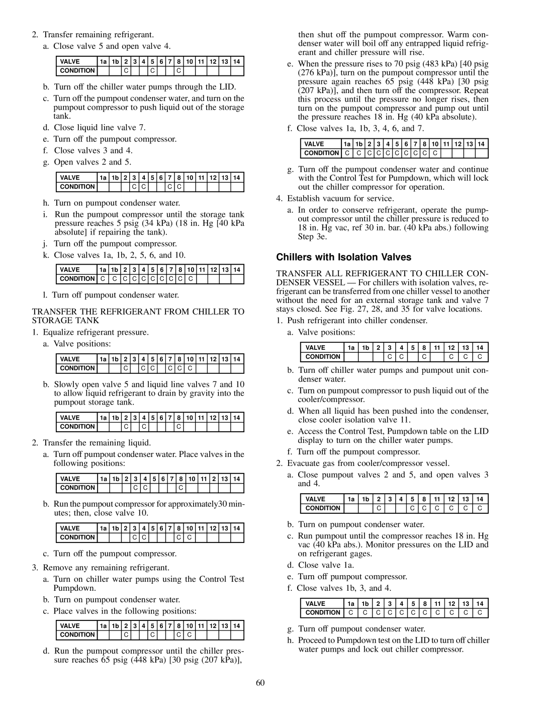
2. Transfer remaining refrigerant.

a. Close valve 5 and open valve 4.

VALVE

1a

1b

2

3

4

5

6

7

8

10

11

12

13

14

CONDITION


C


C


C


b. Turn off the chiller water pumps through the LID.

c. Turn off the pumpout condenser water, and turn on the pumpout compressor to push liquid out of the storage tank.

d. Close liquid line valve 7.

e. Turn off the pumpout compressor. f. Close valves 3 and 4.

g. Open valves 2 and 5.

VALVE

1a

1b

2

3

4

5

6

7

8

10

11

12

13

14

CONDITION


C

C


C

C


h. Turn on pumpout condenser water.

i. Run the pumpout compressor until the storage tank pressure reaches 5 psig (34 kPa) (18 in. Hg [40 kPa absolute] if repairing the tank).

j. Turn off the pumpout compressor. k. Close valves 1a, 1b, 2, 5, 6, and 10.

VALVE

1a

1b

2

3

4

5

6

7

8

10

11

12

13

14

CONDITION

C

C

C

C

C

C

C

C

C

C


l. Turn off pumpout condenser water.

TRANSFER THE REFRIGERANT FROM CHILLER TO STORAGE TANK

1. Equalize refrigerant pressure. a. Valve positions:

VALVE

1a

1b

2

3

4

5

6

7

8

10

11

12

13

14

CONDITION


C


C

C


C

C

C


b. Slowly open valve 5 and liquid line valves 7 and 10 to allow liquid refrigerant to drain by gravity into the pumpout storage tank.

VALVE

1a

1b

2

3

4

5

6

7

8

10

11

12

13

14

CONDITION


C


C


C


2. Transfer the remaining liquid.

a. Turn off pumpout condenser water. Place valves in the following positions:

VALVE

1a

1b

2

3

4

5

6

7

8

10

11

2

13

14

CONDITION


C

C


C


b. Run the pumpout compressor for approximately30 min- utes; then, close valve 10.

VALVE

1a

1b

2

3

4

5

6

7

8

10

11

12

13

14

CONDITION


C

C


C

C


c. Turn off the pumpout compressor.

3. Remove any remaining refrigerant.

a. Turn on chiller water pumps using the Control Test Pumpdown.

b. Turn on pumpout condenser water.

c. Place valves in the following positions:

VALVE

1a

1b

2

3

4

5

6

7

8

10

11

12

13

14

CONDITION


C


C


C

C


d. Run the pumpout compressor until the chiller pres- sure reaches 65 psig (448 kPa) [30 psig (207 kPa)],

then shut off the pumpout compressor. Warm con- denser water will boil off any entrapped liquid refrig- erant and chiller pressure will rise.

e. When the pressure rises to 70 psig (483 kPa) [40 psig (276 kPa)], turn on the pumpout compressor until the pressure again reaches 65 psig (448 kPa) [30 psig (207 kPa)], and then turn off the compressor. Repeat this process until the pressure no longer rises, then turn on the pumpout compressor and pump out until the pressure reaches 18 in. Hg (40 kPa absolute).

f. Close valves 1a, 1b, 3, 4, 6, and 7.

VALVE

1a

1b

2

3

4

5

6

7

8

10

11

12

13

14

CONDITION

C

C

C

C

C

C

C

C

C

C


g. Turn off the pumpout condenser water and continue with the Control Test for Pumpdown, which will lock out the chiller compressor for operation.

4. Establish vacuum for service.

a. In order to conserve refrigerant, operate the pump- out compressor until the chiller pressure is reduced to 18 in. Hg vac, ref 30 in. bar. (40 kPa abs.) following Step 3e.

Chillers with Isolation Valves

TRANSFER ALL REFRIGERANT TO CHILLER CON- DENSER VESSEL Ð For chillers with isolation valves, re- frigerant can be transferred from one chiller vessel to another without the need for an external storage tank and valve 7 stays closed. See Fig. 27, 28, and 35 for valve locations.

1. Push refrigerant into chiller condenser. a. Valve positions:

VALVE

1a

1b

2

3

4

5

8

11

12

13

14

CONDITION


C

C


C


C

C

C


b. Turn off chiller water pumps and pumpout unit con- denser water.

c. Turn on pumpout compressor to push liquid out of the cooler/compressor.

d. When all liquid has been pushed into the condenser, close cooler isolation valve 11.

e. Access the Control Test, Pumpdown table on the LID display to turn on the chiller water pumps.

f. Turn off the pumpout compressor.

2. Evacuate gas from cooler/compressor vessel.

a. Close pumpout valves 2 and 5, and open valves 3 and 4.

VALVE

1a

1b

2

3

4

5

8

11

12

13

14

CONDITION


C


C

C

C

C

C

C


b. Turn on pumpout condenser water.

c. Run pumpout until the compressor reaches 18 in. Hg vac (40 kPa abs.). Monitor pressures on the LID and on refrigerant gages.

d. Close valve 1a.

e. Turn off pumpout compressor. f. Close valves 1b, 3, and 4.

VALVE

1a

1b

2

3

4

5

8

11

12

13

14

CONDITION

C

C

C

C

C

C

C

C

C

C

C


g. Turn off pumpout condenser water.

h. Proceed to Pumpdown test on the LID to turn off chiller water pumps and lock out chiller compressor.

60

Page 60
Image 60
Carrier 19XL specifications Chillers with Isolation Valves, Transfer the Refrigerant from Chiller to Storage Tank

19XL specifications

The Carrier 19XL is a highly regarded commercial heating and cooling solution, designed to provide optimum performance and energy efficiency in various applications. This rooftop unit is engineered to meet the diverse needs of businesses, making it an ideal choice for those requiring reliable climate control in their facilities.

One of the standout features of the Carrier 19XL is its advanced cooling and heating capabilities. The unit utilizes a high-efficiency scroll compressor that ensures a quieter operation and improved reliability. The system can operate across a wide range of temperatures, making it versatile for various climates. Additionally, it offers both cooling and heating options, allowing for year-round comfort.

Energy efficiency is a focal point of the 19XL design. With an impressive Seasonal Energy Efficiency Ratio (SEER) and Heating Seasonal Performance Factor (HSPF), this unit not only helps reduce energy costs but also supports environmental sustainability initiatives. The unit is equipped with environmentally friendly refrigerants, further contributing to lower greenhouse gas emissions.

The Carrier 19XL features a user-friendly control system, allowing for easy monitoring and management of the unit's performance. This control system is designed to maximize energy savings, offering features such as demand control ventilation and integrated economizers that facilitate the use of outdoor air for cooling, reducing reliance on mechanical systems when conditions allow.

Construction-wise, the Carrier 19XL is built to withstand tough environmental conditions. Its robust cabinet is made from galvanized steel, providing durability and protection against the elements. The design also includes insulation to minimize noise levels, creating a more comfortable indoor environment.

Maintenance is a key consideration in the design of the 19XL. The unit features accessible service ports and a simplified access panel, allowing technicians to perform routine maintenance with ease. This proactive design helps ensure the longevity of the system and minimizes downtime, keeping operations running smoothly.

In summary, the Carrier 19XL is an exceptional choice for commercial heating and cooling needs. With its energy-efficient features, advanced technology, and durable construction, it stands out as a reliable solution for businesses looking for sustainable climate control options.