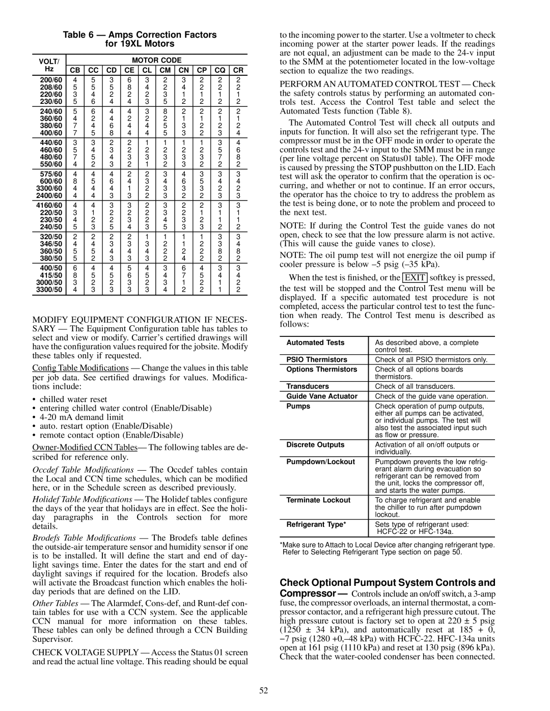
Table 6 Ð Amps Correction Factors
for 19XL Motors
VOLT/ | | | | MOTOR CODE | | | |
Hz | CB | CC | CD | CE | CL | CM | CN | CP | CQ | CR |
200/60 | 4 | 5 | 3 | 6 | 3 | 2 | 3 | 2 | 2 | 2 |
208/60 | 5 | 5 | 5 | 8 | 4 | 2 | 4 | 2 | 2 | 2 |
220/60 | 3 | 4 | 2 | 2 | 2 | 3 | 1 | 1 | 1 | 1 |
230/60 | 5 | 6 | 4 | 4 | 3 | 5 | 2 | 2 | 2 | 2 |
240/60 | 5 | 6 | 4 | 4 | 3 | 8 | 2 | 2 | 2 | 2 |
360/60 | 4 | 2 | 4 | 2 | 2 | 2 | 1 | 1 | 1 | 1 |
380/60 | 7 | 4 | 6 | 4 | 4 | 5 | 3 | 2 | 2 | 2 |
400/60 | 7 | 5 | 8 | 4 | 4 | 5 | 3 | 2 | 3 | 4 |
440/60 | 3 | 3 | 2 | 2 | 1 | 1 | 1 | 1 | 3 | 4 |
460/60 | 5 | 4 | 3 | 2 | 2 | 2 | 2 | 2 | 5 | 6 |
480/60 | 7 | 5 | 4 | 3 | 3 | 3 | 3 | 3 | 7 | 8 |
550/60 | 4 | 2 | 3 | 2 | 1 | 2 | 3 | 2 | 2 | 2 |
575/60 | 4 | 4 | 4 | 2 | 2 | 3 | 4 | 3 | 3 | 3 |
600/60 | 8 | 5 | 6 | 4 | 3 | 4 | 6 | 5 | 4 | 4 |
3300/60 | 4 | 4 | 4 | 1 | 2 | 3 | 3 | 3 | 2 | 2 |
2400/60 | 4 | 4 | 3 | 3 | 2 | 3 | 2 | 2 | 3 | 3 |
4160/60 | 4 | 4 | 3 | 3 | 2 | 3 | 2 | 2 | 3 | 3 |
220/50 | 3 | 1 | 2 | 2 | 2 | 3 | 2 | 1 | 1 | 1 |
230/50 | 4 | 2 | 2 | 3 | 2 | 4 | 3 | 2 | 1 | 1 |
240/50 | 5 | 3 | 5 | 4 | 3 | 5 | 3 | 3 | 2 | 2 |
320/50 | 2 | 2 | 2 | 2 | 1 | 1 | 1 | 1 | 3 | 3 |
346/50 | 4 | 4 | 3 | 3 | 3 | 2 | 1 | 2 | 3 | 4 |
360/50 | 5 | 5 | 4 | 4 | 4 | 2 | 2 | 2 | 8 | 8 |
380/50 | 5 | 2 | 3 | 3 | 3 | 2 | 4 | 2 | 2 | 2 |
400/50 | 6 | 4 | 4 | 5 | 4 | 3 | 6 | 4 | 3 | 3 |
415/50 | 8 | 5 | 5 | 6 | 5 | 4 | 7 | 5 | 4 | 4 |
3000/50 | 3 | 2 | 2 | 3 | 2 | 3 | 1 | 2 | 1 | 2 |
3300/50 | 4 | 3 | 3 | 3 | 3 | 4 | 2 | 2 | 1 | 2 |
MODIFY EQUIPMENT CONFIGURATION IF NECES- SARY Ð The Equipment Con®guration table has tables to select and view or modify. Carrier's certi®ed drawings will have the con®guration values required for the jobsite. Modify these tables only if requested.
Con®g Table Modi®cations Ð Change the values in this table per job data. See certi®ed drawings for values. Modi®ca- tions include:
·chilled water reset
·entering chilled water control (Enable/Disable)
·4-20 mA demand limit
·auto. restart option (Enable/Disable)
·remote contact option (Enable/Disable)
Owner-Modi®ed CCN TablesÐ The following tables are de- scribed for reference only.
Occdef Table Modi®cations Ð The Occdef tables contain the Local and CCN time schedules, which can be modi®ed here, or in the Schedule screen as described previously.
Holidef Table Modi®cations Ð The Holidef tables con®gure the days of the year that holidays are in effect. See the holi- day paragraphs in the Controls section for more details.
Brodefs Table Modi®cations Ð The Brodefs table de®nes the outside-air temperature sensor and humidity sensor if one is to be installed. It will de®ne the start and end of day- light savings time. Enter the dates for the start and end of daylight savings if required for the location. Brodefs also will activate the Broadcast function which enables the holi- day periods that are de®ned on the LID.
Other Tables Ð The Alarmdef, Cons-def, and Runt-def con- tain tables for use with a CCN system. See the applicable CCN manual for more information on these tables. These tables can only be de®ned through a CCN Building Supervisor.
CHECK VOLTAGE SUPPLY Ð Access the Status 01 screen and read the actual line voltage. This reading should be equal
to the incoming power to the starter. Use a voltmeter to check incoming power at the starter power leads. If the readings are not equal, an adjustment can be made to the 24-v input to the SMM at the potentiometer located in the low-voltage section to equalize the two readings.
PERFORM AN AUTOMATED CONTROL TEST Ð Check the safety controls status by performing an automated con- trols test. Access the Control Test table and select the Automated Tests function (Table 8).
The Automated Control Test will check all outputs and inputs for function. It will also set the refrigerant type. The compressor must be in the OFF mode in order to operate the controls test and the 24-v input to the SMM must be in range (per line voltage percent on Status01 table). The OFF mode is caused by pressing the STOP pushbutton on the LID. Each test will ask the operator to con®rm that the operation is oc- curring, and whether or not to continue. If an error occurs, the operator has the choice to try to address the problem as the test is being done, or to note the problem and proceed to the next test.
NOTE: If during the Control Test the guide vanes do not open, check to see that the low pressure alarm is not active. (This will cause the guide vanes to close).
NOTE: The oil pump test will not energize the oil pump if cooler pressure is below ±5 psig (±35 kPa).
When the test is ®nished, or the EXIT softkey is pressed,
the test will be stopped and the Control Test menu will be displayed. If a speci®c automated test procedure is not completed, access the particular control test to test the func- tion when ready. The Control Test menu is described as follows:
Automated Tests | As described above, a complete |
| control test. |
PSIO Thermistors | Check of all PSIO thermistors only. |
Options Thermistors | Check of all options boards |
| thermistors. |
Transducers | Check of all transducers. |
Guide Vane Actuator | Check of the guide vane operation. |
Pumps | Check operation of pump outputs, |
| either all pumps can be activated, |
| or individual pumps. The test will |
| also test the associated input such |
| as ¯ow or pressure. |
Discrete Outputs | Activation of all on/off outputs or |
| individually. |
Pumpdown/Lockout | Pumpdown prevents the low refrig- |
| erant alarm during evacuation so |
| refrigerant can be removed from |
| the unit, locks the compressor off, |
| and starts the water pumps. |
Terminate Lockout | To charge refrigerant and enable |
| the chiller to run after pumpdown |
| lockout. |
Refrigerant Type* | Sets type of refrigerant used: |
| HCFC-22 or HFC-134a. |
*Make sure to Attach to Local Device after changing refrigerant type. Refer to Selecting Refrigerant Type section on page 50.
Check Optional Pumpout System Controls and Compressor Ð Controls include an on/off switch, a 3-amp fuse, the compressor overloads, an internal thermostat, a com- pressor contactor, and a refrigerant high pressure cutout. The high pressure cutout is factory set to open at 220 ± 5 psig (1250 ± 34 kPa), and automatically reset at 185 + 0, −7 psig (1280 +0,±48 kPa) with HCFC-22.HFC-134a units open at 161 psig (1110 kPa) and reset at 130 psig (896 kPa). Check that the water-cooled condenser has been connected.