Start-Up, Operation, and Maintenance Instructions
Safety Considerations
Contents
Contents
Introduction
Abbreviations and Explanations
Chiller Familiarization
Refrigeration Cycle
MOTOR/OIL Refrigeration Cooling Cycle
19XL Rear View
Take-Apart Rabbet Fit Connector
Cooler In/Out Temperature Sensors
Condenser In/Out Temperature Sensors
Cooler Pressure Schrader Fitting
Lubrication Cycle
Refrigerant Motor Cooling and Oil Cooling Cycles
Lubrication System
Starting Equipment
Unit-Mounted Solid-State Starter Optional
Denitions
Controls
Major PIC Components Panel Locations
PIC Component Panel
19XL Controls and Sensor Locations
Pressure Transducer, Typical
Power Panel with Options
Control and OIL Heater Voltage Selector S1
LID Operation and Menus Fig
General
Select
− Example of Point Status Screen Status01
Override Operations
Example of Time Schedule Operation Screen
19XL Menu Structure
19XL Service Menu Structure
19XL Service Menu Structure
Setpoint
Example of Set Point Screen
Description Range Units Reference Point Name Alarm History
LID Screens
Example 1 Ð STATUS01 Display Screen
Menu Status Select
Example 2 Ð STATUS02 Display Screen
Example 3 Ð STATUS03 Display Screen
Example 4 Ð Setpoint Display Screen
Menu
Example 5 Ð Configuration Config Display Screen
Example 6 Ð LEAD/LAG Configuration Display Screen
ECW Control Option
ICE Build Termination
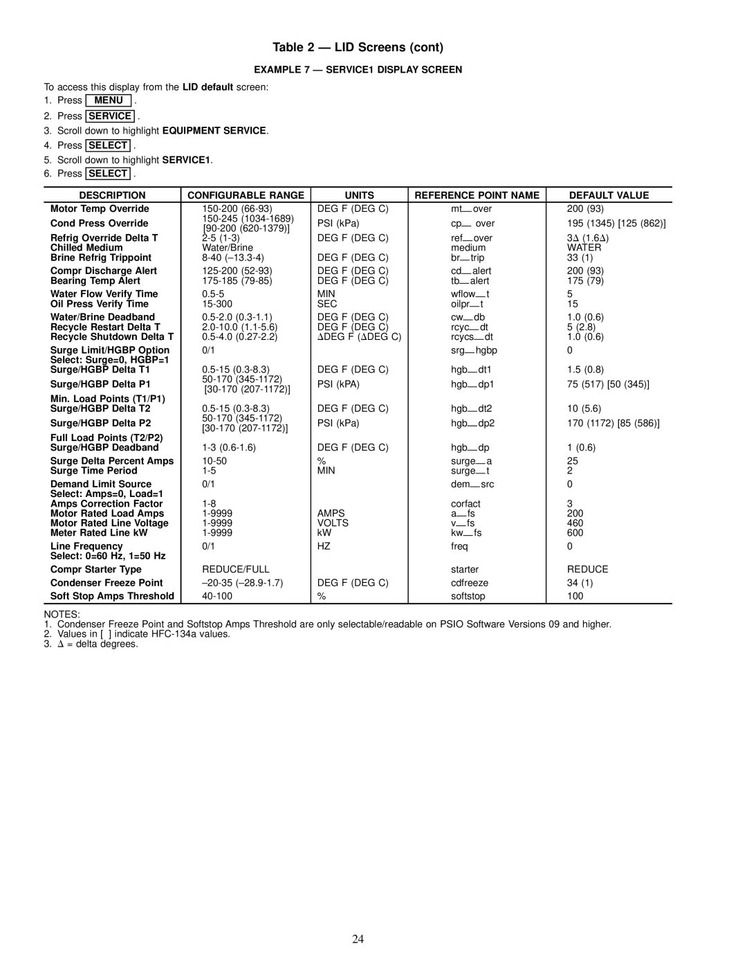
Example 7 Ð SERVICE1 Display Screen
Example 8 Ð SERVICE2 Display Screen
Spare Alert Enable
Example 9 Ð SERVICE3 Display Screen
Menu Service
Example 10 Ð Maintenance MAINT01 Display Screen
Example 11 Ð Maintenance MAINT02 Display Screen
Discharge Temperature
Bearing Temperature
Example 12 Ð Maintenance MAINT03 Display Screen
Example 13 Ð Maintenance MAINT04 Display Screen
Description RANGE/STATUS Units Reference Point Name
PIC System Functions
Page
Protective Safety Limits and Control Settings
Capacity Overrides
Page
Page
Lead/Lag Control
ECW
Hgbp
Hot Gas Bypass
Page
Ice Build Control
Cent Capacity
Page
Example of Attach to Network Device Screen
To LOG on
START-UP/SHUTDOWN/RECYCLE
Sequence Fig
Recycle Restart Delta T
Using the Optional Storage Tank and Pumpout
Before Initial START-UP
Job Data Required
Equipment Required
19XL Leak Test Procedures
Page
Ð HCFC-22 Pressure Ð Temperature F
Ð HCFC-22 Pressure Ð Temperature C
Ð HFC-134a Pressure Ð Temperature F
Ð HFC-134a Pressure Ð Temperature C
Temperature Pressure
Page
Inspect Wiring
Check Optional Pumpout Compressor Water Pip
Check Starter
MECHANICAL-TYPE Starters
Benshaw, Inc. Solid-State Starter Power Stack
BENSHAW, INC. SOLID-STATE Starter
Power Up the Controls and Check the Oil Heater
Set Up Chiller Control Conguration
Load Surge Prevention Occurs TOO Soon Occurs TOO Late
Amps Correction Factors For 19XL Motors
Volt Motor Code
Charge Refrigerant into Chiller
19XL Chiller Equalization Without PUMP- OUT Unit
Control Test Menu Functions
Tests to be Devices Tested Performed
Refrigerant Charges
19XL Total Refrigerant Charge
Cooler
Size
Initial START-UP
Dry Run to Test Start-Up Sequence
Check Rotation
Check Oil Pressure and Compressor Stop
Calibrate Motor Current
Operating Instructions
Operator Duties
To Stop the Chiller
Plant
Pumpout and Refrigerant Transfer Procedures
Operating the Optional Pumpout Compressor
Transfer Refrigerant from Storage Tank to Chiller
Tstat
Chillers with Isolation Valves
Transfer the Refrigerant from Chiller to Storage Tank
General Maintenance
Test After Service, Repair, or Major Leak Ð If
Return Refrigerant to Normal Operating Conditions
Weekly Maintenance
Guide Vane Actuator Linkage
Scheduled Maintenance
Check Safety and Operating Controls Monthly
To Change the OIL
Compressor Bearing and Gear Mainten
Inspect the Heat Exchanger Tubes
Optional Pumpout System Controls
Troubleshooting Guide
MAINT01
MAINT02
MAINT03
MAINT04
Shutdown with ON/OFF/RESET-OFF
Timing OUT or Timed OUT
Recycle Shutdown
Normal or AUTO.-RESTART
Autorestart in Progress
LOW Chilled Water
Normal RUN with RESET, TEMPERATURE, or Demand
Compressor Jumpstart and Refrigerant Protection
Normal RUN Overrides Active Alerts
OUT-OF-RANGE Sensor Failures
Limited
Chiller Protect Limit Faults
Protective Limit
Chiller Alerts
Spare Sensor Alert Messages
Other PROBLEMS/MALFUNCTIONS
DESCRIPTION/MALFUNCTION Probable CAUSE/REMEDY
Ð Thermistor Temperature F vs Resistance/Voltage Drop
Temperature Voltage Resistance Drop
Ð Thermistor Temperature C vs Resistance/Voltage Drop
Control Modules
Module Address
Input Options Module
Starter Management Module SMM Fig
Processor Module Psio Fig
Options Module
Installation
Switch Options Setting Module
Typical Benshaw, Inc. Solid-State Starter internal View
Page
Page
Benshaw, Inc. Solid-State Starter Troubleshooting Guide
Problem Probable Causes Area of Correction
RV1
SCR
Heat Exchanger Data
Additional Data for Marine Waterboxes
Cooler
Condenser
Waterbox Cover Weights
Coolers
Condensers
1034 kPa
Compressor/Motor Weights
Compressor Weights
Optional Pumpout System Electrical Data
Compressor Fits and Clearances
Compressor Assembly Torques
Description Torque
Ft-lb
``Z
CLR
COM
Comm
EXT
Page
CLR
Page
Chiller Power Panel, Starter Assembly Motor Wiring Schematic
Chiller Power Panel, Starter Assembly Motor Wiring Schematic
PMR
POT
GFR
HPS
Typical Wye-Delta Unit Mounted Starter Wiring Schematic
Index
Index
Copyright 1996 Carrier Corporation