Chiller Dehydration Ð Dehydration is recommended if the chiller has been open for a considerable period of time, if the chiller is known to contain moisture, or if there has been a complete loss of chiller holding charge or refrigerant pressure.
Do not start or megohm test the compressor motor or oil pump motor, even for a rotation check, if the chiller is under dehydration vacuum. Insulation breakdown and severe damage may result.
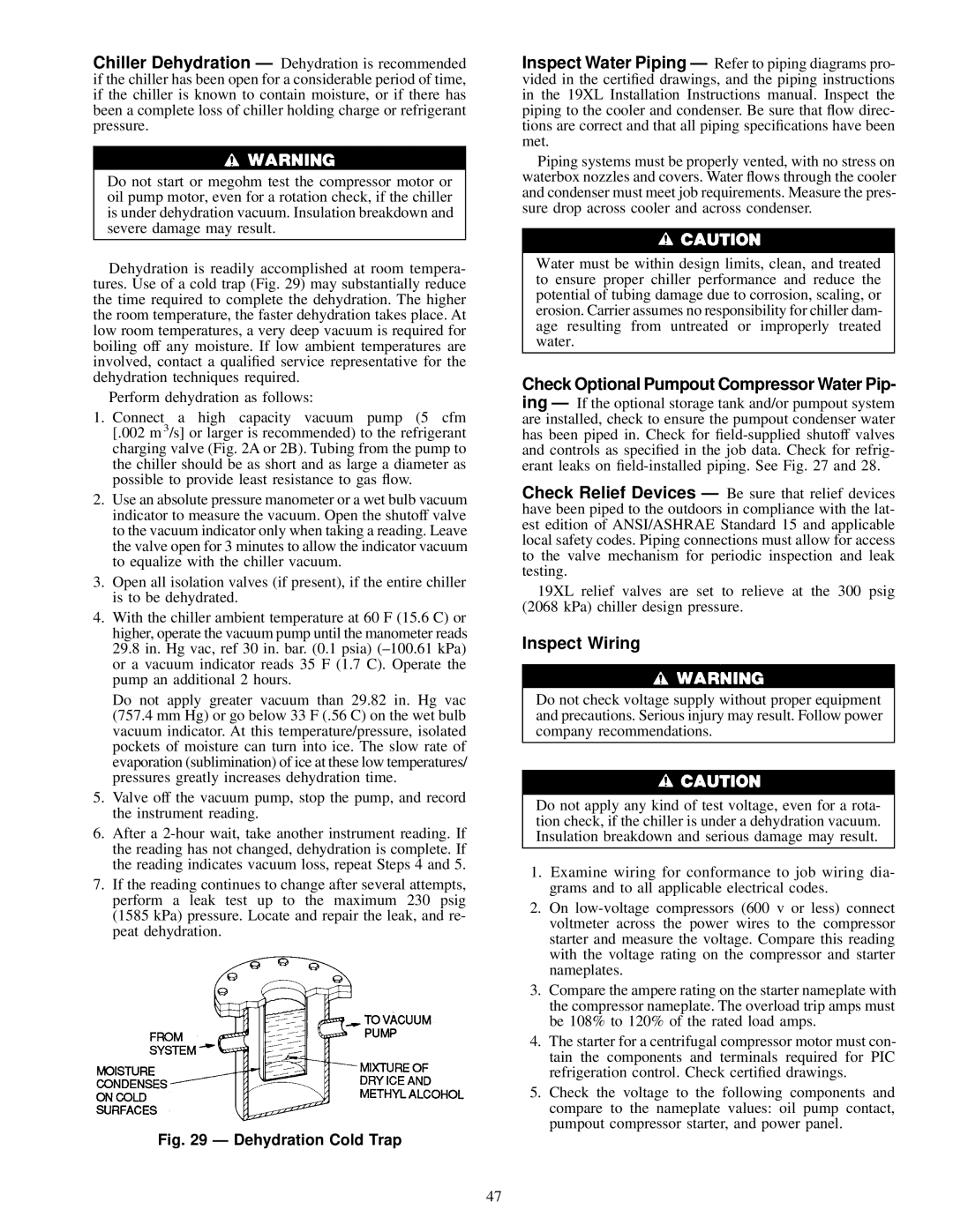
Dehydration is readily accomplished at room tempera- tures. Use of a cold trap (Fig. 29) may substantially reduce the time required to complete the dehydration. The higher the room temperature, the faster dehydration takes place. At low room temperatures, a very deep vacuum is required for boiling off any moisture. If low ambient temperatures are involved, contact a quali®ed service representative for the dehydration techniques required.
Perform dehydration as follows:
1.Connect a high capacity vacuum pump (5 cfm [.002 m 3/s] or larger is recommended) to the refrigerant charging valve (Fig. 2A or 2B). Tubing from the pump to the chiller should be as short and as large a diameter as possible to provide least resistance to gas ¯ow.
2.Use an absolute pressure manometer or a wet bulb vacuum indicator to measure the vacuum. Open the shutoff valve to the vacuum indicator only when taking a reading. Leave the valve open for 3 minutes to allow the indicator vacuum to equalize with the chiller vacuum.
3.Open all isolation valves (if present), if the entire chiller is to be dehydrated.
4.With the chiller ambient temperature at 60 F (15.6 C) or higher, operate the vacuum pump until the manometer reads 29.8 in. Hg vac, ref 30 in. bar. (0.1 psia) (±100.61 kPa) or a vacuum indicator reads 35 F (1.7 C). Operate the pump an additional 2 hours.
Do not apply greater vacuum than 29.82 in. Hg vac (757.4 mm Hg) or go below 33 F (.56 C) on the wet bulb vacuum indicator. At this temperature/pressure, isolated pockets of moisture can turn into ice. The slow rate of evaporation (sublimination) of ice at these low temperatures/ pressures greatly increases dehydration time.
5.Valve off the vacuum pump, stop the pump, and record the instrument reading.
6.After a 2-hour wait, take another instrument reading. If the reading has not changed, dehydration is complete. If the reading indicates vacuum loss, repeat Steps 4 and 5.
7.If the reading continues to change after several attempts, perform a leak test up to the maximum 230 psig (1585 kPa) pressure. Locate and repair the leak, and re- peat dehydration.
Fig. 29 Ð Dehydration Cold Trap
Inspect Water Piping Ð Refer to piping diagrams pro- vided in the certi®ed drawings, and the piping instructions in the 19XL Installation Instructions manual. Inspect the piping to the cooler and condenser. Be sure that ¯ow direc- tions are correct and that all piping speci®cations have been met.
Piping systems must be properly vented, with no stress on waterbox nozzles and covers. Water ¯ows through the cooler and condenser must meet job requirements. Measure the pres- sure drop across cooler and across condenser.
Water must be within design limits, clean, and treated to ensure proper chiller performance and reduce the potential of tubing damage due to corrosion, scaling, or erosion. Carrier assumes no responsibility for chiller dam- age resulting from untreated or improperly treated water.
Check Optional Pumpout Compressor Water Pip-
ing Ð If the optional storage tank and/or pumpout system are installed, check to ensure the pumpout condenser water has been piped in. Check for ®eld-supplied shutoff valves and controls as speci®ed in the job data. Check for refrig- erant leaks on ®eld-installed piping. See Fig. 27 and 28.
Check Relief Devices Ð Be sure that relief devices have been piped to the outdoors in compliance with the lat- est edition of ANSI/ASHRAE Standard 15 and applicable local safety codes. Piping connections must allow for access to the valve mechanism for periodic inspection and leak testing.
19XL relief valves are set to relieve at the 300 psig (2068 kPa) chiller design pressure.
Inspect Wiring
Do not check voltage supply without proper equipment and precautions. Serious injury may result. Follow power company recommendations.
Do not apply any kind of test voltage, even for a rota- tion check, if the chiller is under a dehydration vacuum. Insulation breakdown and serious damage may result.
1.Examine wiring for conformance to job wiring dia- grams and to all applicable electrical codes.
2.On low-voltage compressors (600 v or less) connect voltmeter across the power wires to the compressor starter and measure the voltage. Compare this reading with the voltage rating on the compressor and starter nameplates.
3.Compare the ampere rating on the starter nameplate with the compressor nameplate. The overload trip amps must be 108% to 120% of the rated load amps.
4.The starter for a centrifugal compressor motor must con- tain the components and terminals required for PIC refrigeration control. Check certi®ed drawings.
5.Check the voltage to the following components and compare to the nameplate values: oil pump contact, pumpout compressor starter, and power panel.