2.8 Network Communication Interfaces 2.8.1
The
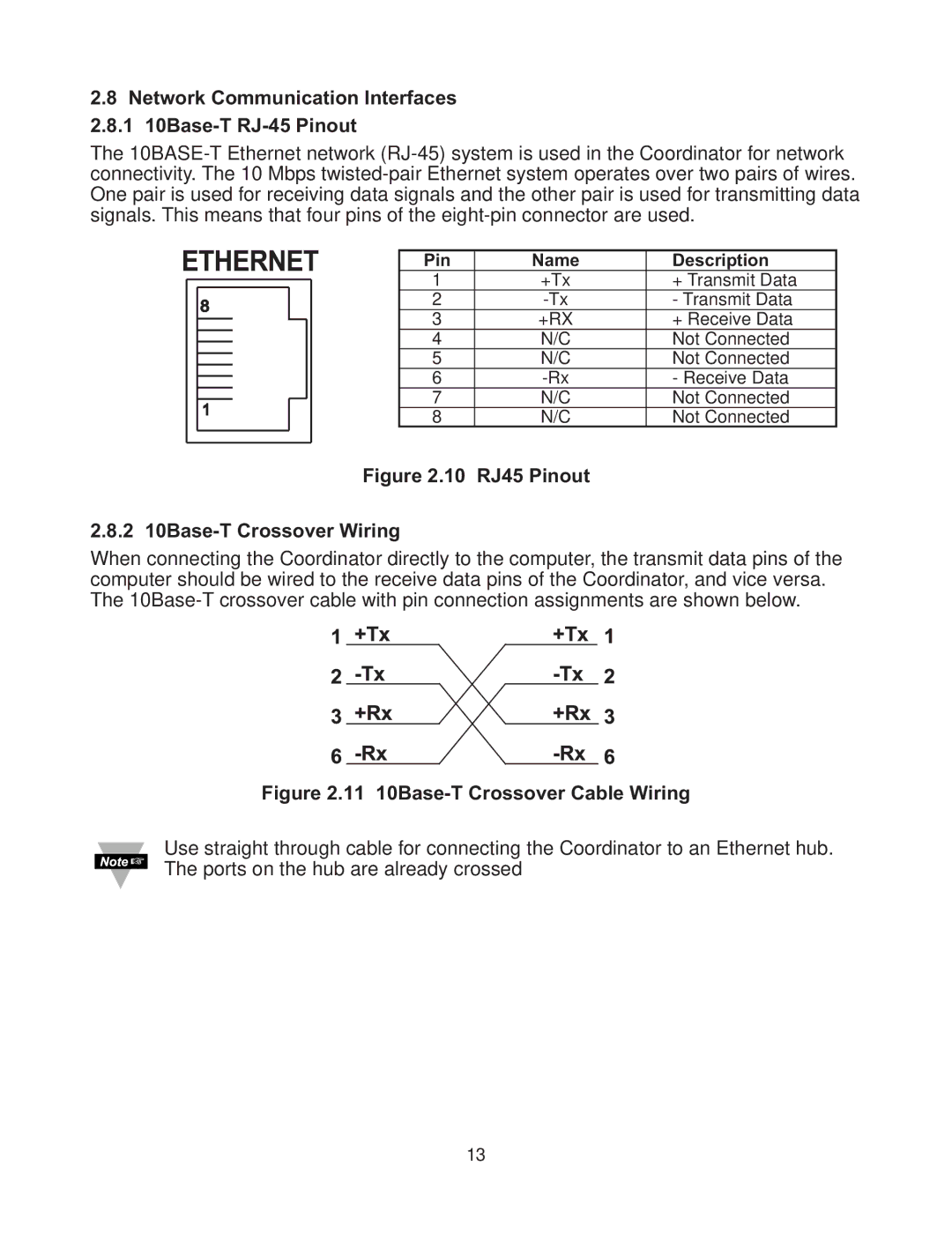
Pin | Name | Description |
1 | +Tx | + Transmit Data |
2 | - Transmit Data | |
3 | +RX | + Receive Data |
4 | N/C | Not Connected |
5 | N/C | Not Connected |
6 | - Receive Data | |
7 | N/C | Not Connected |
8 | N/C | Not Connected |
Figure 2.10 RJ45 Pinout
2.8.2 10Base-T Crossover Wiring
When connecting the Coordinator directly to the computer, the transmit data pins of the computer should be wired to the receive data pins of the Coordinator, and vice versa. The
Figure 2.11 10Base-T Crossover Cable Wiring
Use straight through cable for connecting the Coordinator to an Ethernet hub. The ports on the hub are already crossed
13