Multi-room system connections
U.S.A. and Canadian models (Xantech Multi-Room Systems)
Do not plug in the power cord until all connections have been made.
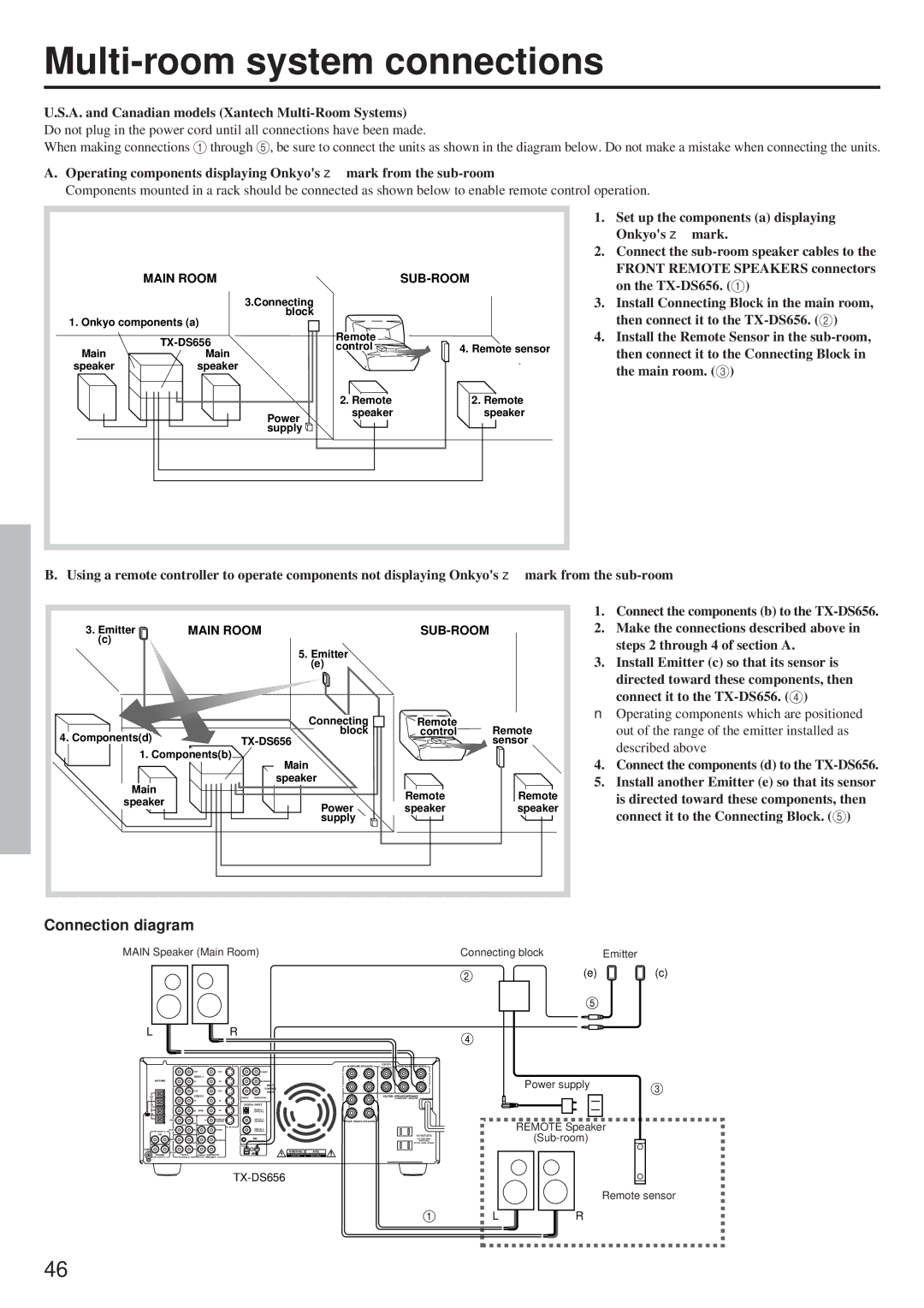
When making connections 1 through 5, be sure to connect the units as shown in the diagram below. Do not make a mistake when connecting the units.
A. Operating components displaying Onkyo's z mark from the |
| ||||
Components mounted in a rack should be connected as shown below to enable remote control operation. | |||||
|
|
|
| 1. Set up the components (a) displaying | |
|
|
|
|
| Onkyo's z mark. |
|
|
|
| 2. Connect the | |
| MAIN ROOM |
|
| FRONT REMOTE SPEAKERS connectors | |
|
|
| on the | ||
|
|
|
|
| |
|
| 3.Connecting |
| 3. | Install Connecting Block in the main room, |
1. Onkyo components (a) | block |
|
| then connect it to the | |
|
|
| |||
|
| Remote | 4. | Install the Remote Sensor in the | |
|
| control | 4. Remote sensor | then connect it to the Connecting Block in | |
Main | Main |
| |||
|
|
| |||
speaker | speaker |
|
|
| the main room. (3) |
|
|
|
|
| |
|
|
| 2. Remote | 2. Remote |
|
|
| Power | speaker | speaker |
|
|
|
|
|
| |
|
| supply |
|
|
|
B. Using a remote controller to operate components not displaying Onkyo's z mark from the
3. Emitter | MAIN ROOM |
| ||
(c) |
|
|
| |
| 5. Emitter |
|
| |
| (e) |
|
| |
| Connecting | Remote | Remote | |
4. Components(d) | block | control | ||
| sensor | |||
1. Components(b) |
|
| ||
| Main |
|
| |
Main | speaker |
|
| |
| Remote | Remote | ||
speaker |
| |||
Power | speaker | speaker | ||
| ||||
| supply |
|
| |
1.Connect the components (b) to the
2.Make the connections described above in steps 2 through 4 of section A.
3.Install Emitter (c) so that its sensor is directed toward these components, then connect it to the
■Operating components which are positioned out of the range of the emitter installed as described above
4.Connect the components (d) to the TX-DS656.
5.Install another Emitter (e) so that its sensor is directed toward these components, then connect it to the Connecting Block. (5)
Connection diagram
MAIN Speaker (Main Room) | Connecting block | Emitter |
(e)(c)
L |
|
| R |
|
|
|
|
|
|
|
|
|
|
| MJ |
| CENTER |
|
|
R | L | V | S |
| SURROUND SPEAKERS | FRONT MAIN | SPEAKERS | ||
| SPEAKER | ||||||||
| OUT | OUT |
| FRONT |
|
|
|
|
|
|
| R | L |
|
|
|
|
| |
ANTENNA | IN | IN |
| SURROUND | R | L |
| R | L |
|
| R |
| L | MULTI |
|
| OUT | OUT |
| CHANNEL |
| |
|
|
| INPUT |
| ||
AM | CENTER | SUBWOOFER |
| CAUTION: SPEAKER IMPEDANCE | ||
|
|
| 6 OHMS MIN. / SPEAKER | |||
| IN | IN |
|
|
|
|
FM |
|
| DIGITAL INPUT | R | L | |
75 |
|
|
|
| ||
| IN DVD | IN |
| DIGITAL 1 |
|
|
FM |
|
|
|
|
|
|
300 |
|
|
|
|
|
|
(REC) | V | MONITOR |
| DIGITAL 2 | FRONT REMOTE SPEAKERS | |
OUTPUT |
| (COAXIAL) | ||||
|
| OUT |
|
|
|
|
| S | |
|
|
|
| |
R | (PLAY) | IN | FRONT | DIGITAL 3 |
L |
|
| (COAXIAL) | |
| CD | R | L | AC OUTLETS |
(REC) |
|
| SURROUND |
|
| AC 120V 60Hz |
| OUT | R | L |
| REMOTE CONTROL | TOTAL 120W 1A MAX. |
|
| OUT | IN |
| ||
GND | IN |
|
|
| WARNING | AVIS |
(PLAY) |
|
|
|
|
PHONO |
| CENTER SUBWOOFER | RISK OF ELECTRIC SHOCK | RISQUE DE CHOC ELECTRIQUE | ||
R | L | R | L | PRE OUT |
|
|
Power supply
REMOTE Speaker
Remote sensor
LR
46