Multi-room system connections
Models other than U.S.A. and Canadian models (Onkyo
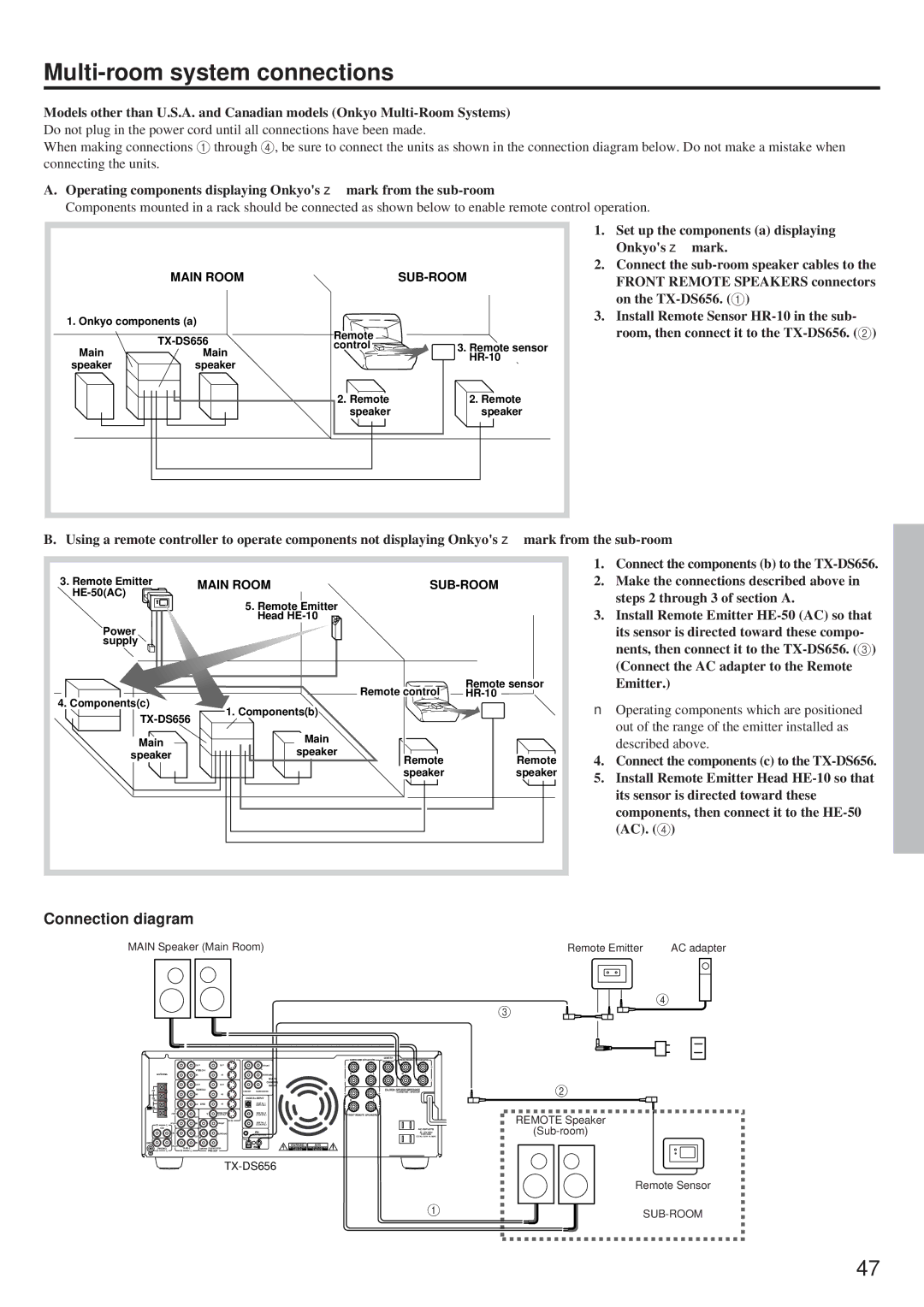
Do not plug in the power cord until all connections have been made.
When making connections 1 through 4, be sure to connect the units as shown in the connection diagram below. Do not make a mistake when connecting the units.
A. Operating components displaying Onkyo's z mark from the |
| |||
Components mounted in a rack should be connected as shown below to enable remote control operation. | ||||
|
|
|
| 1. Set up the components (a) displaying |
|
|
|
| Onkyo's z mark. |
| MAIN ROOM |
| 2. Connect the | |
|
| FRONT REMOTE SPEAKERS connectors | ||
|
|
|
| on the |
1. Onkyo components (a) |
|
| 3. Install Remote Sensor | |
|
| room, then connect it to the | ||
| Remote |
| ||
| control | 3. Remote sensor |
| |
Main | Main |
| ||
|
| |||
speaker | speaker |
|
| |
|
|
| ||
|
| 2. Remote | 2. Remote |
|
|
| speaker | speaker |
|
B. Using a remote controller to operate components not displaying Onkyo's z mark from the
3. Remote Emitter | MAIN ROOM | |||
|
|
| ||
| 5. Remote Emitter |
|
| |
| Head |
|
| |
Power |
|
|
| |
supply |
|
|
| |
|
| Remote control | Remote sensor | |
4. Components(c) |
| |||
1. Components(b) |
|
| ||
|
| |||
|
|
| ||
Main | Main |
|
| |
speaker |
|
| ||
speaker | Remote | Remote | ||
| ||||
|
| |||
|
| speaker | speaker | |
1.Connect the components (b) to the
2.Make the connections described above in steps 2 through 3 of section A.
3.Install Remote Emitter
■Operating components which are positioned out of the range of the emitter installed as described above.
4.Connect the components (c) to the
5.Install Remote Emitter Head
Connection diagram
MAIN Speaker (Main Room) | Remote Emitter | AC adapter |
3
4
|
|
|
|
|
| MJ |
| CENTER |
|
|
R | L | V | S |
|
| SURROUND SPEAKERS | SPEAKER | FRONT MAIN | SPEAKERS | |
| OUT |
| OUT |
| FRONT |
|
|
|
|
|
|
|
| R | L |
|
|
|
|
| |
ANTENNA | IN |
| IN |
| SURROUND | R | L |
| R | L |
|
| R |
| L | MULTI |
|
| OUT | OUT |
| CHANNEL |
| |
|
|
| INPUT |
| ||
AM | CENTER | SUBWOOFER |
| CAUTION: SPEAKER IMPEDANCE | ||
|
|
| 6 OHMS MIN. / SPEAKER | |||
| IN | IN |
|
|
|
|
FM |
|
| DIGITAL INPUT | R | L | |
75 |
|
|
|
| ||
| IN DVD | IN |
| DIGITAL 1 |
|
|
FM |
| (OPTICAL) |
|
| ||
300 |
|
|
|
|
|
|
(REC) | V | MONITOR |
| DIGITAL 2 | FRONT REMOTE SPEAKERS | |
OUTPUT |
| (COAXIAL) | ||||
|
| OUT |
|
|
|
|
| S | |
R | (PLAY) | IN | FRONT | DIGITAL 3 |
L |
|
| (COAXIAL) | |
| CD | R | L | AC OUTLETS |
(REC) |
|
| SURROUND |
|
| AC 120V 60Hz |
| OUT | R | L |
| REMOTE CONTROL | TOTAL 120W 1A MAX. |
|
| OUT | IN |
| ||
GND | IN |
|
|
| WARNING | AVIS |
(PLAY) |
|
|
|
|
PHONO |
| CENTER SUBWOOFER | RISK OF ELECTRIC SHOCK | RISQUE DE CHOC ELECTRIQUE | ||
R | L | R | L | PRE OUT |
|
|
1
2
REMOTE Speaker
Remote Sensor
47