iRIS 220 / iRIS 320, V1.19 User Guide - 18
3.5 Antenna Connection
The iRIS can be supplied with an optional ground plane independent dipole antenna.
∙iRIS 220 antenna connects to a female BNC connector that protrudes through the end of the case.
∙iRIS 320 / iRIS 320V antenna is fitted through a compression gland in the bottom of the case. Internally, the antenna terminates at a female BNC connector on the circuit board.
In areas of marginal coverage, this antenna can be removed and replaced with an external high gain antenna such as a Yagi, via appropriate
3.6 Mounting – iRIS 220
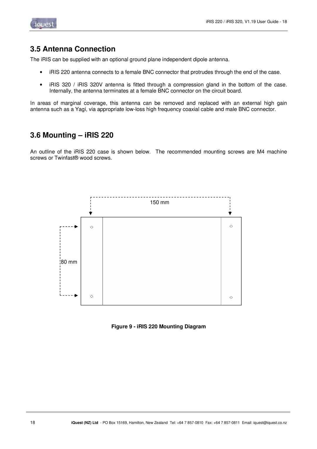
An outline of the iRIS 220 case is shown below. The recommended mounting screws are M4 machine screws or Twinfast® wood screws.
150 mm
80 mm
Figure 9 - iRIS 220 Mounting Diagram
18 | iQuest (NZ) Ltd - PO Box 15169, Hamilton, New Zealand Tel: +64 7 |