iRIS 220 / iRIS 320, V1.19 User Guide - 68
13.3 SDI-12 Interface
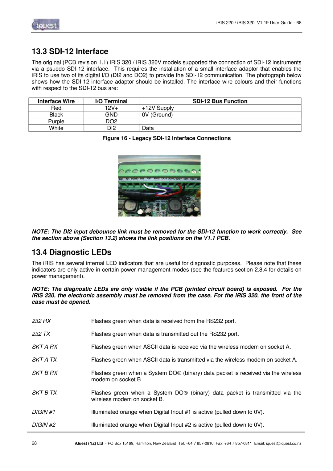
The original (PCB revision 1.1) iRIS 320 / iRIS 320V models supported the connection of
Interface Wire | I/O Terminal |
|
Red | 12V+ | +12V Supply |
Black | GND | 0V (Ground) |
Purple | DO2 |
|
White | DI2 | Data |
Figure 16 - Legacy SDI-12 Interface Connections
NOTE: The DI2 input debounce link must be removed for the
13.4 Diagnostic LEDs
The iRIS has several internal LED indicators that are useful for diagnostic purposes. Please note that these indicators are only active in certain power management modes (see the features section 2.8.4 for details on power management).
NOTE: The diagnostic LEDs are only visible if the PCB (printed circuit board) is exposed. For the iRIS 220, the electronic assembly must be removed from the case. For the iRIS 320, the front of the case must be opened.
232 RX | Flashes green when data is received from the RS232 port. |
232 TX | Flashes green when data is transmitted out the RS232 port. |
SKT A RX | Flashes green when ASCII data is received via the wireless modem on socket A. |
SKT A TX | Flashes green when ASCII data is transmitted via the wireless modem on socket A. |
SKT B RX | Flashes green when a System DO (binary) data packet is received via the wireless |
| modem on socket B. |
SKT B TX | Flashes green when a System DO (binary) data packet is transmitted via the |
| wireless modem on socket B. |
DIGIN #1 | Illuminated orange when Digital Input #1 is active (pulled down to 0V). |
DIGIN #2 | Illuminated orange when Digital Input #2 is active (pulled down to 0V). |
|
|
68 | iQuest (NZ) Ltd - PO Box 15169, Hamilton, New Zealand Tel: +64 7 |