iRIS 220 / iRIS 320, V1.19 User Guide - 54
6.2 Connecting a 0-5V Pressure Transducer
Connecting a standard sensor (such as a pressure transducer that provides a
However, the iRIS 320’s internal battery is NOT recommended for directly powering the sensor alone if the charging source is a solar panel, as it is a relatively low capacity type. Connect a supplementary external 12V battery (7A/Hr or larger) to increase the available storage.
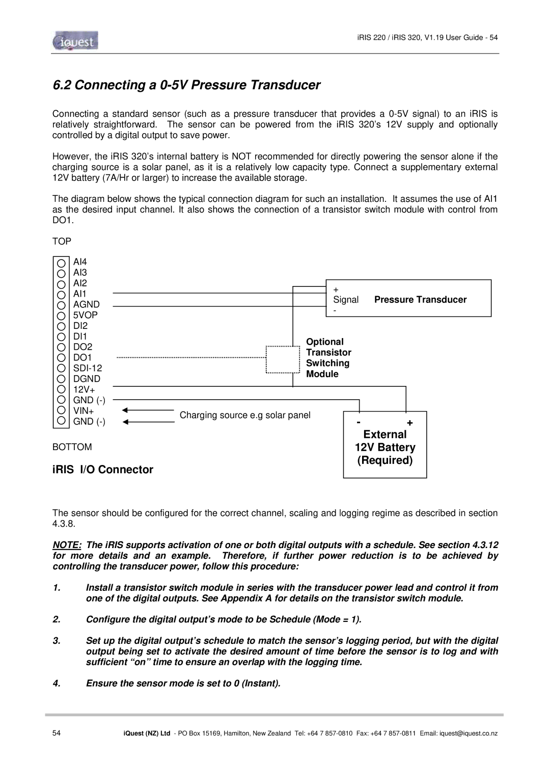
The diagram below shows the typical connection diagram for such an installation. It assumes the use of AI1 as the desired input channel. It also shows the connection of a transistor switch module with control from DO1.
TOP |
|
|
| |
AI4 |
|
|
| |
AI3 |
|
|
| |
AI2 | + |
|
| |
AI1 |
| Pressure Transducer | ||
Signal | ||||
AGND | ||||
- |
|
| ||
5VOP |
|
| ||
|
|
| ||
DI2 |
|
|
| |
DI1 | Optional |
|
| |
DO2 |
|
| ||
Transistor |
|
| ||
DO1 |
|
| ||
Switching |
|
| ||
|
| |||
Module |
|
| ||
DGND |
|
| ||
|
|
| ||
12V+ |
|
|
| |
GND |
|
|
| |
VIN+ | Charging source e.g solar panel | - | + | |
GND | ||||
| ||||
|
|
| External | |
BOTTOM |
| 12V Battery | ||
|
| (Required) | ||
iRIS I/O Connector
The sensor should be configured for the correct channel, scaling and logging regime as described in section 4.3.8.
NOTE: The iRIS supports activation of one or both digital outputs with a schedule. See section 4.3.12 for more details and an example. Therefore, if further power reduction is to be achieved by controlling the transducer power, follow this procedure:
1.Install a transistor switch module in series with the transducer power lead and control it from one of the digital outputs. See Appendix A for details on the transistor switch module.
2.Configure the digital output’s mode to be Schedule (Mode = 1).
3.Set up the digital output’s schedule to match the sensor’s logging period, but with the digital output being set to activate the desired amount of time before the sensor is to log and with sufficient “on” time to ensure an overlap with the logging time.
4.Ensure the sensor mode is set to 0 (Instant).
54 | iQuest (NZ) Ltd - PO Box 15169, Hamilton, New Zealand Tel: +64 7 |