63 - iRIS 220 / iRIS 320, V1.19 User Guide
10 Appendix A – Radio Using the RS232 Interface
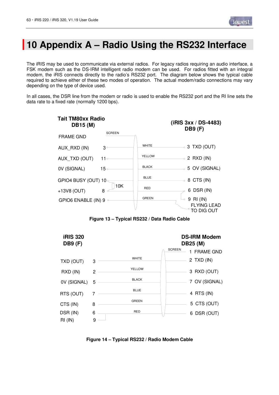
The iRIS may be used to communicate via external radios. For legacy radios requiring an audio interface, a FSK modem such as the
In all cases, the DSR line from the modem or radio is used to enable the RS232 port and the RI line sets the data rate to a fixed rate (normally 1200 bps).
Tait TM80xx Radio
DB15 (M)(iRIS 3xx / DS-4483)
DB9 (F)
SCREEN
FRAME GND
AUX_RXD (IN) | 3 |
| WHITE |
|
| ||
AUX_TXD (OUT) | 11 |
| YELLOW |
|
| ||
0V (SIGNAL) | 15 |
| BLACK |
|
| ||
GPIO4 BUSY (OUT) 10 |
| BLUE | |
|
| ||
+13V8 (OUT) | 8 | 10K | RED |
| |||
|
| ||
![]() 3 TXD (OUT)
3 TXD (OUT)
2 RXD (IN)
5 OV (SIGNAL)
8 CTS (IN)
6 DSR (IN)
GPIO6 ENABLE (IN) 9 ![]()
GREEN
9 RI (IN)
FLYING LEAD ![]() TO DIG OUT
TO DIG OUT
Figure 13 – Typical RS232 / Data Radio Cable
iRIS 320 DB9 (F)
TXD (OUT) | 3 |
RXD (IN) | 2 |
0V (SIGNAL) | 5 |
RTS (OUT) | 7 |
CTS (IN) | 8 |
DSR (IN) | 6 |
RI (IN) | 9 |
DS-IRM Modem
DB25 (M)
| SCREEN | 1 FRAME GND |
WHITE |
| |
| 2 TXD (IN) | |
|
| |
YELLOW |
| 3 RXD (OUT) |
|
| |
BLACK |
| 7 OV (SIGNAL) |
|
| |
BLUE |
| 4 RTS (IN) |
|
| |
GREEN |
| 5 CTS (OUT) |
|
| |
RED |
| 6 DSR (OUT) |
|
|