INSTALLATION PROCEDURE
In the following installation procedure, we assume you are using a Compumotor motor with your
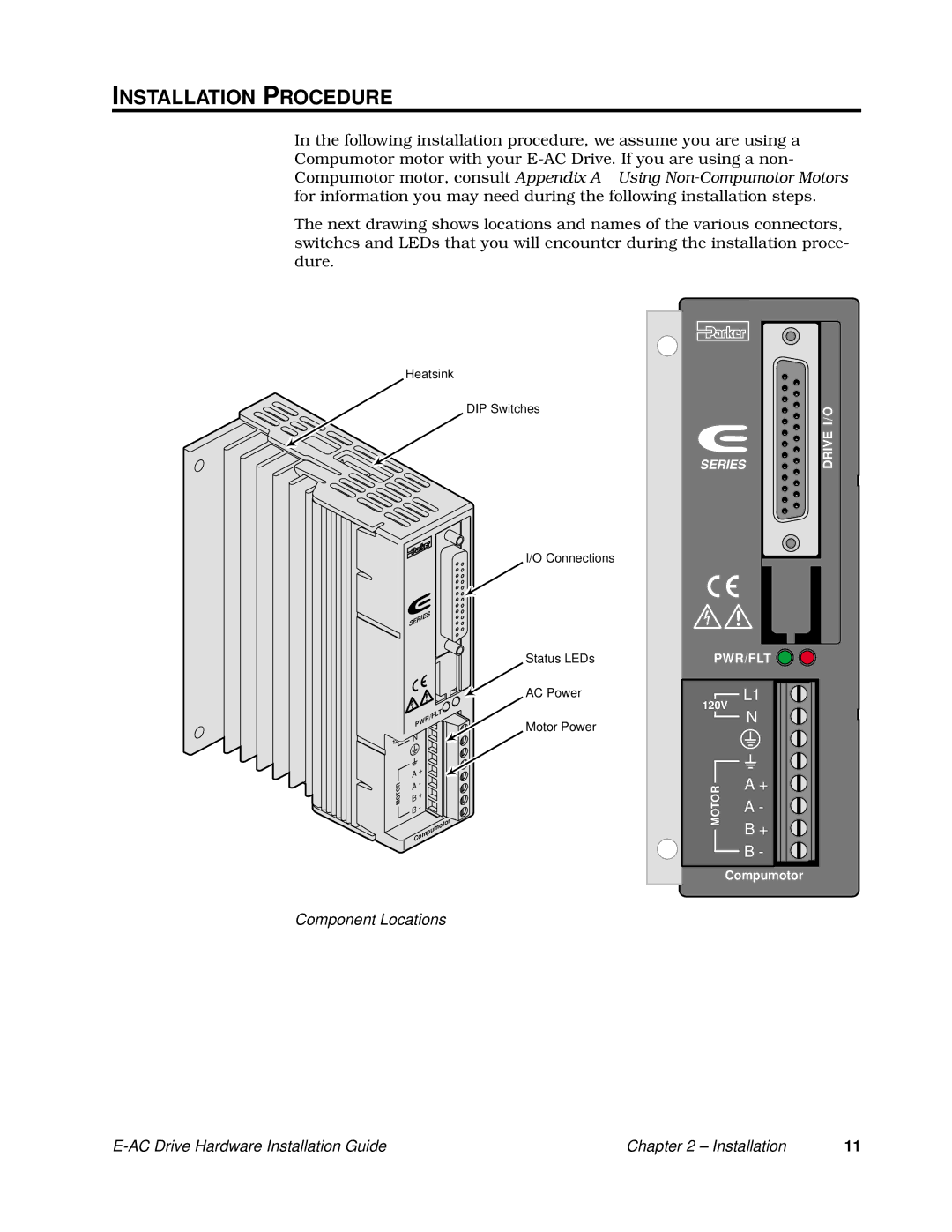
The next drawing shows locations and names of the various connectors, switches and LEDs that you will encounter during the installation proce- dure.
Heatsink
DIP Switches
I/O Connections
RESET+ 11 |
| ||
RESET– 23 |
| ||
FLT C | 9 |
| |
FLT E | 21 |
| |
SD – | 17 |
| |
SD + | 16 |
| |
DIR – | 15 |
| |
DIR + | 2 | I/O | |
STEP – 14 | |||
STEP + | 1 | ||
DRIVE | |||
SERIES |
| ||
SERIES
PWR/FLT
V | N |
|
120 |
|
|
| A | + |
| - | |
MOTOR | A | |
| + | |
| B | |
| - | |
| B | |
|
|
| pu | m | otor |
|
| ||
|
|
| |
C | om |
|
|
Status LEDs
AC Power
Motor Power
PWR/FLT | ||
| L1 | |
120V | ||
| N | |
MOTOR | A + | |
A - | ||
B + | ||
| ||
| B - | |
| Compumotor | |
Component Locations
| Chapter 2 – Installation | 11 |