If you use a screw terminal cable breakout device, be sure to properly enclose all exposed conductors to avoid contamination and to reduce the risk of electrostatic discharge. I/O must utilize high quality shielded cabling (85% braid coverage minimum), which must be RF earth bonded as shown above.
Panel Mounting the E-AC Drive
The mounting panel must be properly earthed and paint must be removed from drive mounting locations. You must fasten the motor shield (braid) close to the drive’s heatsink.
If you use a screw terminal cable breakout device, be sure to properly enclose all exposed conductors to avoid contamination and to reduce the risk of electrostatic discharge. I/O must utilize high quality shielded cabling (85% braid coverage minimum), which must be RF earth bonded as shown above.
System Installation
If you mount the
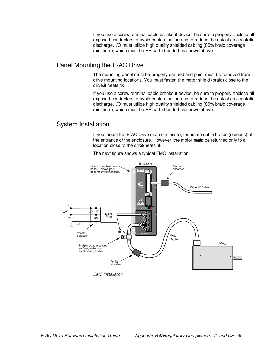
The next figure shows a typical EMC installation.
Mount to earthed metal panel. Remove paint from mounting locations.
L1
VAC | Mains |
| |
N | Filter |
| |
| Earth |
Varistor
(3 places)
| I/O | |
| DRIVE | |
SERIES | ||
PWR/FLT | ||
| L1 | |
120V | ||
| N | |
MOTOR | A + | |
A - | ||
B + | ||
| ||
| B - | |
| Compumotor | |
Ferrite absorber
Drive I/O Cable
Motor
Cable
Motor
P clip braid to mounting surface; make loop
as short as possible
Ferrite ![]() absorber
absorber
EMC Installation
Appendix B – Regulatory Compliance: UL and CE 45 |