E-AC DRIVE –DESCRIPTION
The
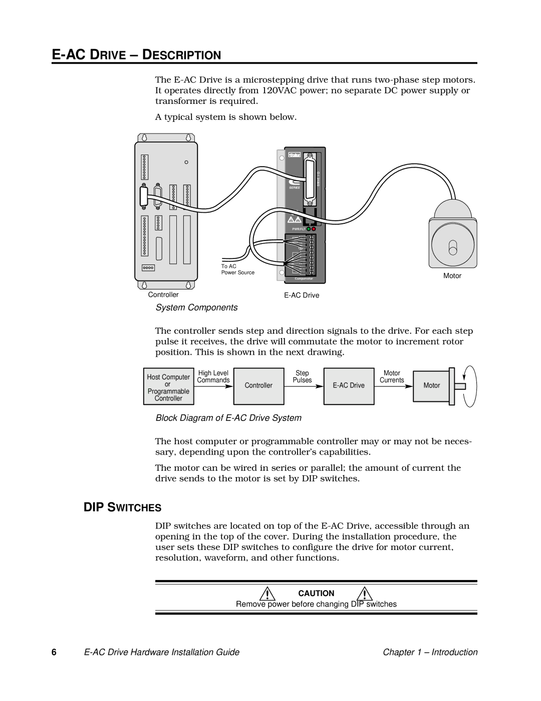
A typical system is shown below.
To AC
Power Source
Controller
System Components
I/O
DRIVE
SERIES
PWR/FLT
L1
120V
N
MOTOR | A + |
|
A - |
| |
| B + |
|
| B - | Motor |
| Compumotor |
The controller sends step and direction signals to the drive. For each step pulse it receives, the drive will commutate the motor to increment rotor position. This is shown in the next drawing.
|
|
|
|
|
|
|
| High Level |
| Step |
|
| Motor | |
Host Computer |
|
|
|
| ||||||||||
| Commands |
| Pulses |
|
| Currents | ||||||||
|
|
| or |
|
|
|
|
|
|
| ||||
|
|
|
|
|
|
| Controller |
|
|
| Motor | |||
| Programmable |
|
|
|
|
|
|
|
| |||||
|
| Controller |
|
|
|
|
|
|
|
|
|
| ||
Block Diagram of E-AC Drive System
The host computer or programmable controller may or may not be neces- sary, depending upon the controller’s capabilities.
The motor can be wired in series or parallel; the amount of current the drive sends to the motor is set by DIP switches.
DIP SWITCHES
DIP switches are located on top of the
CAUTION
Remove power before changing DIP switches
6 |
| Chapter 1 – Introduction |
