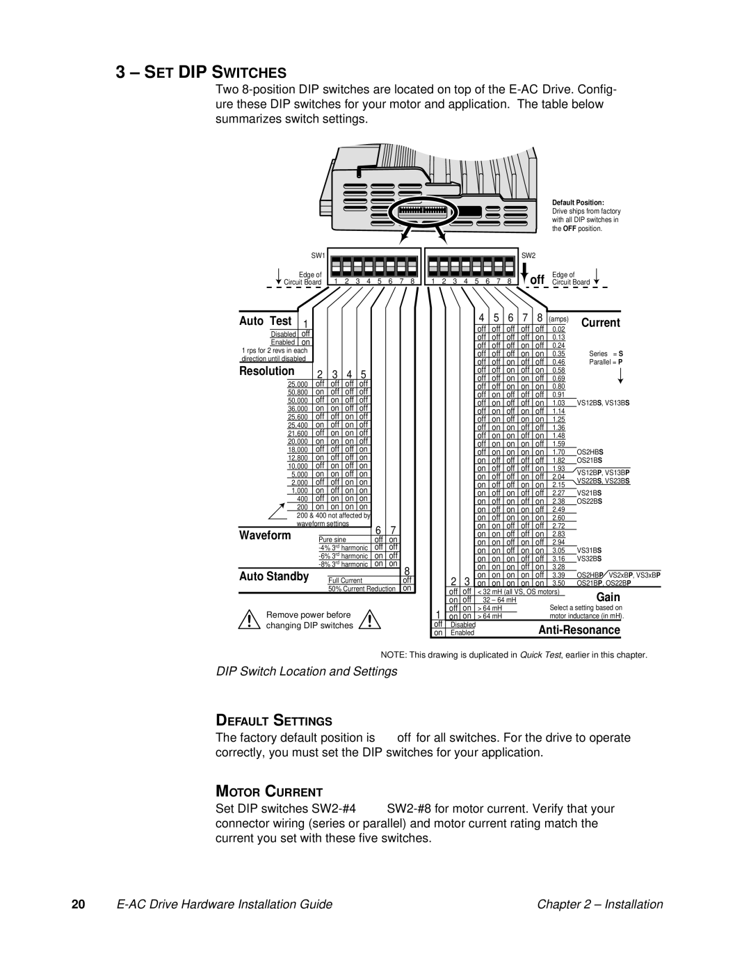
3–SET DIP SWITCHES
Two
SW1 | |
Edge of | 1 2 3 4 5 6 7 8 |
Circuit Board | |
Auto Test | 1 |
|
|
|
| ||
| Disabled | off |
|
|
|
| |
| Enabled | on |
|
|
|
| |
1 rps for 2 revs in each |
|
|
|
| |||
direction until disabled |
|
|
|
| |||
Resolution |
| 2 | 3 | 4 | 5 | ||
| 25,000 | off | off | off | off | ||
| 50,800 | on | off | off | off | ||
| 50,000 | off | on | off | off | ||
| 36,000 | on | on | off | off | ||
| 25,600 | off | off | on | off | ||
| 25,400 | on | off | on | off | ||
| 21,600 | off | on | on | off | ||
| 20,000 | on | on | on | off | ||
| 18,000 | off | off | off | on | ||
| 12,800 | on | off | off | on | ||
| 10,000 | off | on | off | on | ||
| 5,000 | on | on | off | on | ||
| 2,000 | off | off | on | on | ||
1,000 | on | off | on | on | |||
400off on on on
200on on on on
200& 400 not affected by waveform settings
Waveform |
|
| 6 | 7 |
|
|
Pure sine | off | on | ||||
| off | off | ||||
| on | off | ||||
| on | on | ||||
Auto Standby |
|
|
|
|
| 8 |
|
|
|
| |||
| Full Current |
|
|
| off | |
|
| 50% Current Reduction |
| on | ||
Remove power before changing DIP switches
|
|
|
|
|
|
|
|
|
|
|
|
|
|
|
| Default Position: | ||||||||
|
|
|
|
|
|
|
|
|
|
|
|
|
|
|
| Drive ships from factory | ||||||||
|
|
|
|
|
|
|
|
|
|
|
|
|
|
|
| |||||||||
|
|
|
|
|
|
|
|
|
|
|
|
|
|
|
| with all DIP switches in | ||||||||
|
|
|
|
|
|
|
|
|
|
|
|
|
|
|
| the OFF position. | ||||||||
|
|
|
|
|
|
|
|
|
|
|
| SW2 |
| Edge of |
|
|
|
|
|
| ||||
|
|
|
|
|
|
|
|
|
|
|
|
|
|
|
|
|
|
| ||||||
|
|
|
|
|
|
|
|
|
|
|
|
| off |
|
|
|
|
|
|
| ||||
|
|
|
|
|
|
|
|
|
|
|
|
|
|
|
|
|
|
|
| |||||
|
|
|
|
|
|
|
|
|
|
|
|
|
|
|
|
|
|
|
| |||||
| 1 | 2 | 3 | 4 | 5 | 6 | 7 | 8 |
|
|
| Circuit Board |
|
| ||||||||||
|
|
|
|
| ||||||||||||||||||||
|
|
|
|
|
| 4 | 5 |
| 6 |
| 7 |
| 8 |
|
|
|
|
|
|
|
|
|
| |
|
|
|
|
|
|
|
|
|
| (amps) |
| Current | ||||||||||||
|
|
|
|
|
| off | off |
| off | off |
| off | 0.02 |
|
|
| ||||||||
|
|
|
|
|
|
|
|
|
|
|
|
|
|
|
| |||||||||
|
|
|
|
|
| off | off |
| off | off |
| on | 0.13 |
|
|
|
|
|
|
|
| |||
|
|
|
|
|
| off | off |
| off | on |
| off | 0.24 |
|
|
| Series = S | |||||||
|
|
|
|
|
| off | off |
| off | on |
| on | 0.35 |
|
|
| ||||||||
|
|
|
|
|
| off | off |
| on | off |
| off | 0.46 |
|
|
| Parallel = P | |||||||
|
|
|
|
|
| off | off |
| on | off |
| on | 0.58 |
|
|
|
|
|
|
|
| |||
|
|
|
|
|
|
|
|
|
|
|
| |||||||||||||
|
|
|
|
|
| off | off |
| on | on |
| off | 0.69 |
|
|
|
|
|
|
|
| |||
|
|
|
|
|
|
|
|
|
|
|
| |||||||||||||
|
|
|
|
|
| off | off |
| on | on |
| on | 0.80 |
|
|
|
|
|
|
|
| |||
|
|
|
|
|
| off | on |
| off | off |
| off | 0.91 |
|
|
| VS12BS, VS13BS | |||||||
|
|
|
|
|
| off | on |
| off | off |
| on | 1.03 |
|
|
| ||||||||
|
|
|
|
|
| off | on |
| off | on |
| off | 1.14 |
|
|
|
|
|
|
|
| |||
|
|
|
|
|
| off | on |
| off | on |
| on | 1.25 |
|
|
|
|
|
|
|
| |||
|
|
|
|
|
| off | on |
| on | off |
| off | 1.36 |
|
|
|
|
|
|
|
| |||
|
|
|
|
|
| off | on |
| on | off |
| on | 1.48 |
|
|
|
|
|
|
|
| |||
|
|
|
|
|
| off | on |
| on | on |
| off | 1.59 |
|
|
| OS2HBS | |||||||
|
|
|
|
|
| off | on |
| on | on |
| on | 1.70 |
|
|
| ||||||||
|
|
|
|
|
| on | off |
| off | off |
| off | 1.82 |
|
|
| OS21BS | |||||||
|
|
|
|
|
| on | off |
| off | off |
| on | 1.93 |
|
|
| VS12BP, VS13BP | |||||||
|
|
|
|
|
| on | off |
| off | on |
| off | 2.04 |
|
|
| ||||||||
|
|
|
|
|
|
|
|
|
|
| VS22BS, VS23BS | |||||||||||||
|
|
|
|
|
| on | off |
| off | on |
| on | 2.15 |
|
|
| ||||||||
|
|
|
|
|
|
|
|
|
|
| VS21BS | |||||||||||||
|
|
|
|
|
| on | off |
| on | off |
| off | 2.27 |
|
|
| ||||||||
|
|
|
|
|
| on | off |
| on | off |
| on | 2.38 |
|
|
| OS22BS | |||||||
|
|
|
|
|
| on | off |
| on | on |
| off | 2.49 |
|
|
|
|
|
|
|
| |||
|
|
|
|
|
| on | off |
| on | on |
| on | 2.60 |
|
|
|
|
|
|
|
| |||
|
|
|
|
|
| on | on |
| off | off |
| off | 2.72 |
|
|
|
|
|
|
|
| |||
|
|
|
|
|
| on | on |
| off | off |
| on | 2.83 |
|
|
|
|
|
|
|
| |||
|
|
|
|
|
| on | on |
| off | on |
| off | 2.94 |
|
|
| VS31BS | |||||||
|
|
|
|
|
| on | on |
| off | on |
| on | 3.05 |
|
|
| ||||||||
|
|
|
|
|
| on | on |
| on | off |
| off | 3.16 |
|
|
| VS32BS | |||||||
|
|
|
|
|
| on | on |
| on | off |
| on | 3.28 |
|
|
| OS2HBP VS2xBP, VS3xBP | |||||||
|
|
| 2 | 3 | on | on |
| on | on |
| off | 3.39 |
|
|
| |||||||||
|
|
| on | on |
| on | on |
| on | 3.50 |
|
|
| OS21BP | , OS22BP | |||||||||
|
|
| off | off | < 32 mH (all VS, OS motors) |
|
| Gain | ||||||||||||||||
|
|
| on | off |
| 32 – 64 mH |
|
|
|
|
|
|
|
|
| |||||||||
| 1 | off | on | > 64 mH |
|
|
|
|
|
|
| Select a setting based on | ||||||||||||
| on | on | > 64 mH |
|
|
|
|
|
|
| motor inductance (in mH). | |||||||||||||
| off | Disabled |
|
|
|
|
|
|
| |||||||||||||||
| on | Enabled |
|
|
|
|
|
|
|
| ||||||||||||||
NOTE: This drawing is duplicated in Quick Test, earlier in this chapter.
DIP Switch Location and Settings
DEFAULT SETTINGS
The factory default position is off for all switches. For the drive to operate correctly, you must set the DIP switches for your application.
MOTOR CURRENT
Set DIP switches
20 |
| Chapter 2 – Installation |