AUTOMATIC TEST
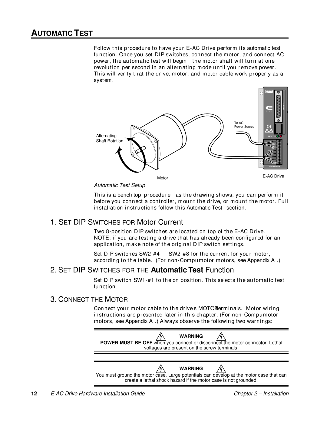
Follow this procedure to have your E-AC Drive perform its automatic test function. Once you set DIP switches, connect the motor, and connect AC power, the automatic test will begin—the motor shaft will turn at one revolution per second in an alternating mode until you remove power. This will verify that the drive, motor, and motor cable work properly as a system.
To AC
Power Source
Alternating
Shaft Rotation
I/O

 DRIVE SERIES

PWR/FLT
L1
120V
N
Compumotor
Automatic Test Setup
This is a bench top procedure—as the drawing shows, you can perform it before you connect a controller, mount the drive, or mount the motor. Full installation instructions follow this Automatic Test section.
1. SET DIP SWITCHES FOR Motor Current
Two 8-position DIP switches are located on top of the E-AC Drive. NOTE: if you are testing a drive that has already been configured for an application, make note of the original DIP switch settings.
Set DIP switches SW2-#4 — SW2-#8 for the current for your motor, according to the table. (For non-Compumotor motors, see Appendix A.)
2.SET DIP SWITCHES FOR THE Automatic Test Function
Set DIP switch SW1-#1 to the on position. This selects the automatic test function.
3.CONNECT THE MOTOR
Connect your motor cable to the drive’s MOTOR terminals. Motor wiring instructions are presented later in this chapter. (For non-Compumotor motors, see Appendix A.) Always observe the following two warnings:
WARNING
POWER MUST BE OFF when you connect or disconnect the motor connector. Lethal
voltages are present on the screw terminals!
WARNING
You must ground the motor case. Large potentials can develop at the motor case that can
create a lethal shock hazard if the motor case is not grounded.
12 | E-AC Drive Hardware Installation Guide | Chapter 2 – Installation |