TERMINAL CONNECTIONS
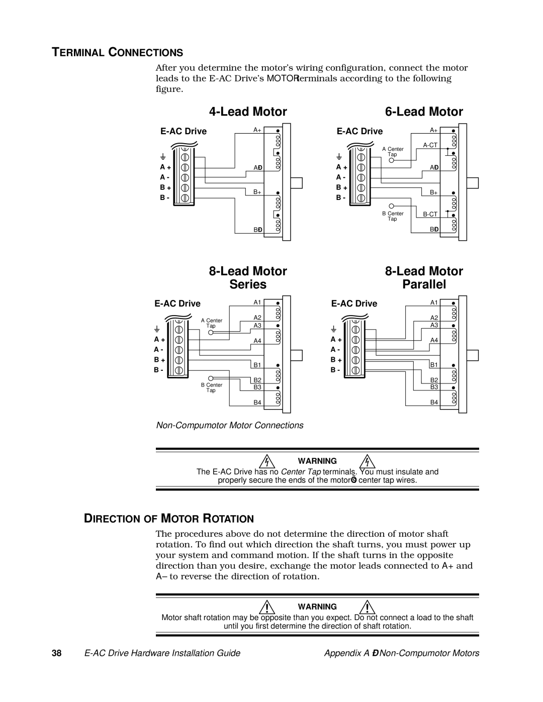
After you determine the motor’s wiring configuration, connect the motor leads to the
A+ | ||
A + | A– | |
A - |
| |
B + | B+ | |
B - | ||
| ||
| B– |
A+ | |
A Center | |
| |
Tap |
|
A + | A– |
A-
B+
B - | B+ |
| |
B Center | |
Tap |
|
B–
| Series | |
A1 | ||
A Center | A2 | |
A3 | ||
Tap | ||
A + | A4 | |
A-
B+
B1
B -
B2
B CenterB3
Tap
B4
| |
| Parallel |
A1 | |
| A2 |
| A3 |
A + | A4 |
A-
B+
B1
B -
B2
B3
B4
Non-Compumotor Motor Connections
WARNING
The
properly secure the ends of the motor’s center tap wires.
DIRECTION OF MOTOR ROTATION
The procedures above do not determine the direction of motor shaft rotation. To find out which direction the shaft turns, you must power up your system and command motion. If the shaft turns in the opposite direction than you desire, exchange the motor leads connected to A+ and A– to reverse the direction of rotation.
WARNING
Motor shaft rotation may be opposite than you expect. Do not connect a load to the shaft
until you first determine the direction of shaft rotation.
38 | Appendix A – |