Cable Shielding
All cables must maintain high integrity 360 degree shielding, and be constructed with at least 85% braid coverage. When you install inputs and outputs, you must observe proper noise immunity standards. See the EMC Installation drawing at the end of this appendix.
Ferrite Absorbers
To meet the requirements of the EMC directive, you must add
Steward Ferrite | part number 28A2024 |
part number 0443164151 |
(These ferrites are available from Compumotor, part number
Enclosure Mounting the E-AC Drive
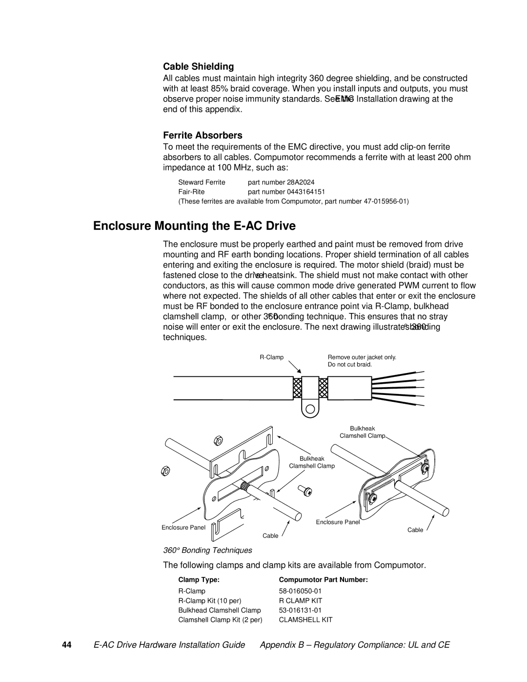
The enclosure must be properly earthed and paint must be removed from drive mounting and RF earth bonding locations. Proper shield termination of all cables entering and exiting the enclosure is required. The motor shield (braid) must be fastened close to the drive’s heatsink. The shield must not make contact with other conductors, as this will cause common mode drive generated PWM current to flow where not expected. The shields of all other cables that enter or exit the enclosure must be RF bonded to the enclosure entrance point via
Remove outer jacket only. | |
| Do not cut braid. |
Bulkheak
Clamshell Clamp
Bulkheak
Clamshell Clamp
Enclosure Panel | Enclosure Panel | |
Cable | ||
| ||
| Cable |
360° Bonding Techniques
The following clamps and clamp kits are available from Compumotor.
Clamp Type: | Compumotor Part Number: |
R CLAMP KIT | |
Bulkhead Clamshell Clamp | |
Clamshell Clamp Kit (2 per) | CLAMSHELL KIT |
44 |