2–CONNECT THE MOTOR TO THE DRIVE –WIRING
Most Compumotor motor
These two
GROUND THE MOTOR CASE
The motor case must be grounded, for safety purposes. On ![]() on the drive’s motor connector. Inside the drive,
on the drive’s motor connector. Inside the drive, ![]() connects directly to the ground pin on the AC power terminals.
connects directly to the ground pin on the AC power terminals.
PRECAUTIONS
Follow these precautions when you wire the motor connector.
1.Turn off power to the drive before connecting or disconnecting the motor leads.
2.Verify that no wire whiskers short out motor connections.
3.Do not apply power to the drive when the motor is not connected.
4.Never connect anything other than the motor to the motor terminals.
5.After wiring the motor connector, perform the Automatic Test, to verify that the connector is wired correctly.
CONNECTING THE MOTOR: SERIES WIRING
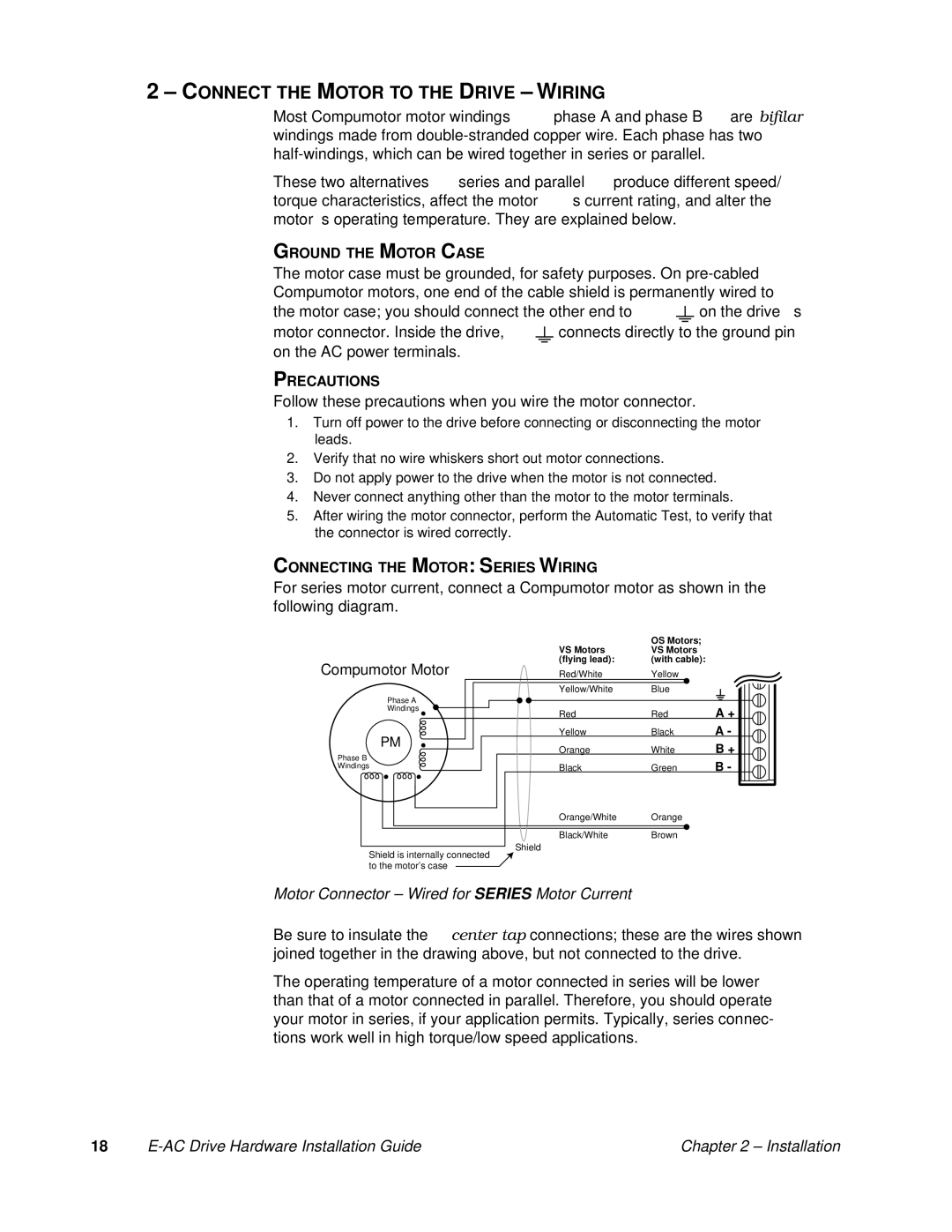
For series motor current, connect a Compumotor motor as shown in the following diagram.
Compumotor Motor
| OS Motors; |
VS Motors | VS Motors |
(flying lead): | (with cable): |
Red/White | Yellow |
Yellow/White | Blue |
| Phase A |
|
|
| Windings | Red | A + |
| Red | ||
| Yellow | Black | A - |
| PM | White | B + |
Phase B | Orange | ||
|
| B - | |
Windings | Black | Green |
Orange/White Orange
Black/White Brown
Shield
Shield is internally connected to the motor’s case
Motor Connector – Wired for SERIES Motor Current
Be sure to insulate the center tap connections; these are the wires shown joined together in the drawing above, but not connected to the drive.
The operating temperature of a motor connected in series will be lower than that of a motor connected in parallel. Therefore, you should operate your motor in series, if your application permits. Typically, series connec- tions work well in high torque/low speed applications.
18 |
| Chapter 2 – Installation |
