SW1
Edge of ![]() Circuit Board
Circuit Board
1 2 3 4 5 6 7 8
1 2 3 4 5 6 7 8
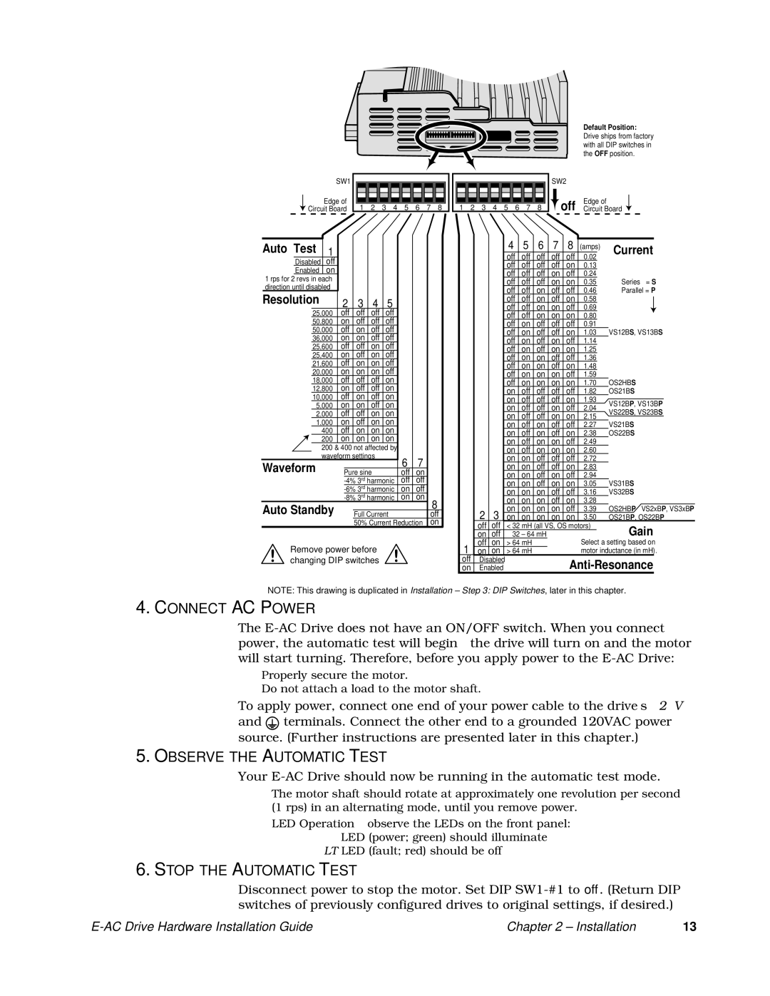
Default Position:
Drive ships from factory with all DIP switches in the OFF position.
SW2
Edge of
off Circuit Board ![]()
Auto Test | 1 |
|
|
|
| ||
| Disabled | off |
|
|
|
| |
| Enabled | on |
|
|
|
| |
1 rps for 2 revs in each |
|
|
|
| |||
direction until disabled |
|
|
|
| |||
Resolution |
| 2 | 3 | 4 | 5 | ||
| 25,000 | off | off | off | off | ||
| 50,800 | on | off | off | off | ||
| 50,000 | off | on | off | off | ||
| 36,000 | on | on | off | off | ||
| 25,600 | off | off | on | off | ||
| 25,400 | on | off | on | off | ||
| 21,600 | off | on | on | off | ||
| 20,000 | on | on | on | off | ||
| 18,000 | off | off | off | on | ||
| 12,800 | on | off | off | on | ||
| 10,000 | off | on | off | on | ||
| 5,000 | on | on | off | on | ||
| 2,000 | off | off | on | on | ||
1,000 | on | off | on | on | |||
400off on on on
200on on on on
200& 400 not affected by waveform settings
Waveform |
|
| 6 | 7 |
|
|
Pure sine | off | on | ||||
| off | off | ||||
| on | off | ||||
| on | on | ||||
Auto Standby |
|
|
|
|
| 8 |
|
|
|
| |||
| Full Current |
|
|
| off | |
|
| 50% Current Reduction |
| on | ||
Remove power before changing DIP switches
|
|
|
| 4 | 5 | 6 | 7 | 8 |
|
|
|
|
|
|
|
|
|
|
| (amps) |
|
| Current | ||||||||
|
|
|
| off | off | off | off | off | 0.02 |
|
|
| |||
|
|
|
|
|
|
|
|
|
| ||||||
|
|
|
| off | off | off | off | on | 0.13 |
|
|
|
|
|
|
|
|
|
| off | off | off | on | off | 0.24 |
|
|
| Series = S | ||
|
|
|
| off | off | off | on | on | 0.35 |
|
|
| |||
|
|
|
| off | off | on | off | off | 0.46 |
|
|
| Parallel = P | ||
|
|
|
| off | off | on | off | on | 0.58 |
|
|
|
|
|
|
|
|
|
|
|
|
|
|
| |||||||
|
|
|
| off | off | on | on | off | 0.69 |
|
|
|
|
|
|
|
|
|
| off | off | on | on | on | 0.80 |
|
|
|
|
|
|
|
|
|
| off | on | off | off | off | 0.91 |
|
|
| VS12BS, VS13BS | ||
|
|
|
| off | on | off | off | on | 1.03 |
|
|
| |||
|
|
|
| off | on | off | on | off | 1.14 |
|
|
|
|
|
|
|
|
|
| off | on | off | on | on | 1.25 |
|
|
|
|
|
|
|
|
|
| off | on | on | off | off | 1.36 |
|
|
|
|
|
|
|
|
|
| off | on | on | off | on | 1.48 |
|
|
|
|
|
|
|
|
|
| off | on | on | on | off | 1.59 |
|
|
| OS2HBS | ||
|
|
|
| off | on | on | on | on | 1.70 |
|
|
| |||
|
|
|
| on | off | off | off | off | 1.82 |
|
|
| OS21BS | ||
|
|
|
| on | off | off | off | on | 1.93 |
|
|
| VS12BP, VS13BP | ||
|
|
|
| on | off | off | on | off | 2.04 |
|
|
| |||
|
|
|
|
|
|
| VS22BS, VS23BS | ||||||||
|
|
|
| on | off | off | on | on | 2.15 |
|
|
| |||
|
|
|
|
|
|
| VS21BS | ||||||||
|
|
|
| on | off | on | off | off | 2.27 |
|
|
| |||
|
|
|
| on | off | on | off | on | 2.38 |
|
|
| OS22BS | ||
|
|
|
| on | off | on | on | off | 2.49 |
|
|
|
|
|
|
|
|
|
| on | off | on | on | on | 2.60 |
|
|
|
|
|
|
|
|
|
| on | on | off | off | off | 2.72 |
|
|
|
|
|
|
|
|
|
| on | on | off | off | on | 2.83 |
|
|
|
|
|
|
|
|
|
| on | on | off | on | off | 2.94 |
|
|
| VS31BS | ||
|
|
|
| on | on | off | on | on | 3.05 |
|
|
| |||
|
|
|
| on | on | on | off | off | 3.16 |
|
|
| VS32BS | ||
|
|
|
| on | on | on | off | on | 3.28 |
|
|
| OS2HBP VS2xBP, VS3xBP | ||
| 2 | 3 |
| on | on | on | on | off | 3.39 |
|
|
| |||
|
| on | on | on | on | on | 3.50 |
|
|
| OS21BP | , OS22BP | |||
| off | off |
| < 32 mH (all VS, OS motors) |
|
| Gain | ||||||||
| on | off |
| 32 – 64 mH |
|
|
|
|
|
| |||||
1 | off | on |
| > 64 mH |
|
|
| Select a setting based on | |||||||
on | on |
| > 64 mH |
|
|
| motor inductance (in mH). | ||||||||
off | Disabled |
|
|
|
|
| |||||||||
on | Enabled |
|
|
|
| ||||||||||
NOTE: This drawing is duplicated in Installation – Step 3: DIP Switches, later in this chapter.
4.CONNECT AC POWER
The
•Properly secure the motor.
•Do not attach a load to the motor shaft.
To apply power, connect one end of your power cable to the drive’s 120V and ![]() terminals. Connect the other end to a grounded 120VAC power source. (Further instructions are presented later in this chapter.)
terminals. Connect the other end to a grounded 120VAC power source. (Further instructions are presented later in this chapter.)
5.OBSERVE THE AUTOMATIC TEST
Your
•The motor shaft should rotate at approximately one revolution per second (1 rps) in an alternating mode, until you remove power.
•LED Operation – observe the LEDs on the front panel:
PWR LED (power; green) should illuminate
FLT LED (fault; red) should be off
6.STOP THE AUTOMATIC TEST
Disconnect power to stop the motor. Set DIP
| Chapter 2 – Installation | 13 |