as metal shavings or grinding dust, can damage the
PANEL LAYOUT
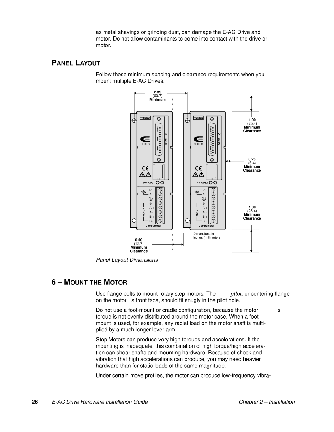
Follow these minimum spacing and clearance requirements when you mount multiple
2.39
(60.7)
Minimum
| I/O |
SERIES | DRIVE |
PWR/FLT
L1
120V
N
|
| A + | |
MOTOR | |||
A - | |||
|
| ||
|
| B + | |
|
| B - | |
|
| ||
Compumotor
0.50
(12.7)
Minimum
Clearance
Panel Layout Dimensions
1.00
(25.4)
Minimum
Clearance
| I/O |
SERIES | DRIVE |
0.25
(6.4)
Minimum
Clearance
PWR/FLT
L1
120V
N
MOTOR | A + | 1.00 |
| Minimum | |
| A - | (25.4) |
|
| |
| B + | Clearance |
| B - | |
|
| |
| Compumotor |
|
Dimensions in |
| |
inches (millimeters) |
| |
6–MOUNT THE MOTOR
Use flange bolts to mount rotary step motors. The pilot, or centering flange on the motor’s front face, should fit snugly in the pilot hole.
Do not use a
Step Motors can produce very high torques and accelerations. If the mounting is inadequate, this combination of high torque/high accelera- tion can shear shafts and mounting hardware. Because of shock and vibration that high accelerations can produce, you may need heavier hardware than for static loads of the same magnitude.
Under certain move profiles, the motor can produce
26 |
| Chapter 2 – Installation |