4–CONNECT A CONTROLLER –INPUTS & OUTPUTS
Connect your controller cable to the DRIVE I/O connector, a 25 pin D- connector on the front of the drive. The cable that comes with Compu- motor controllers is prewired for compatibility with the
SERIES
I/O |
DRIVE |
PWR/FLT
|
| L1 |
| 120V | |
|
| N |
| MOTOR | A + |
| A - | |
|
| B + |
|
| B - |
|
| Compumotor |
Controller | ||
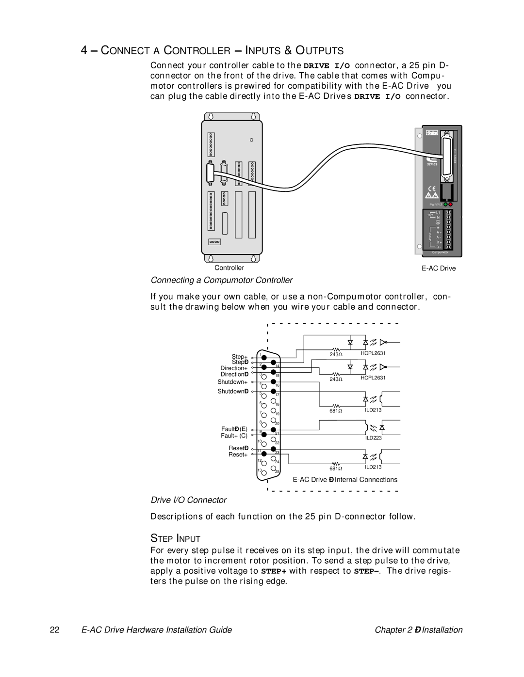
Connecting a Compumotor Controller
If you make your own cable, or use a
Step+ | 1 | 243Ω | HCPL2631 |
|
|
| |
Step– | 2 | 14 |
|
Direction+ |
| ||
|
| ||
|
|
| |
Direction– | 3 | 15 | HCPL2631 |
Shutdown+ | 4 | 243Ω | |
16 |
| ||
|
|
| |
Shutdown– | 5 | 17 |
|
|
|
| |
| 6 | 18 |
|
|
|
| |
| 7 | 681Ω | ILD213 |
|
| 19 |
|
| 8 | 20 |
|
Fault– (E) |
|
| |
9 | 21 |
| |
Fault+ (C) |
| ||
| ILD223 | ||
|
| ||
| 10 | 22 | |
|
| ||
Reset– |
|
| |
11 | 23 |
| |
Reset+ |
| ||
|
| ||
|
|
| |
| 12 | 24 |
|
|
| ILD213 | |
| 13 | 681Ω | |
|
| 25 |
|
Drive I/O Connector
Descriptions of each function on the 25 pin
STEP INPUT
For every step pulse it receives on its step input, the drive will commutate the motor to increment rotor position. To send a step pulse to the drive, apply a positive voltage to STEP+ with respect to
22 |
| Chapter 2 – Installation |