Scenario #2 — The resistance measurement to the second of the three motor leads measures 50% of the resistance measurement to the third of the three motor leads. Label the second motor lead A CENTER TAP (this is the center tap lead for Phase A of the motor). Label the third motor lead
7.Repeat the procedure as outlined in step 6 for the three leads labeled B (B CENTER TAP is the center tap lead for Phase B of the motor).
8.Proceed to the Terminal Connections section below.
8-LEAD MOTOR
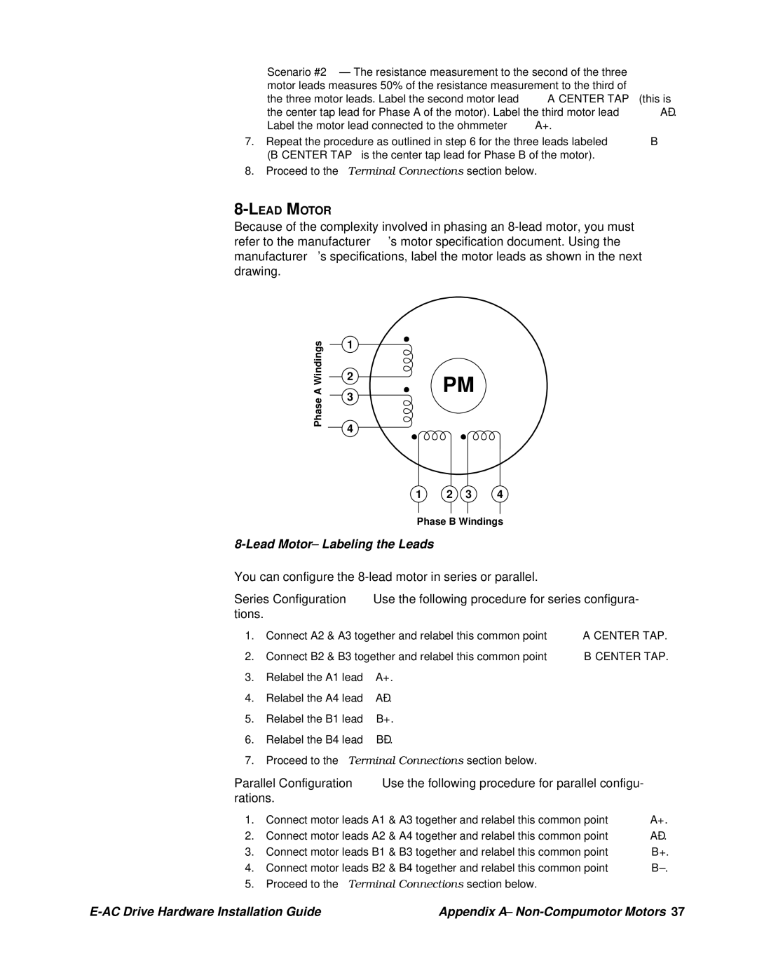
Because of the complexity involved in phasing an
Phase A Windings
1
2
3
4
PM
1 2 3 4
Phase B Windings
8-Lead Motor – Labeling the Leads
You can configure the
Series Configuration Use the following procedure for series configura- tions.
1.Connect A2 & A3 together and relabel this common point A CENTER TAP.
2.Connect B2 & B3 together and relabel this common point B CENTER TAP.
3.Relabel the A1 lead A+.
4.Relabel the A4 lead
5.Relabel the B1 lead B+.
6.Relabel the B4 lead
7.Proceed to the Terminal Connections section below.
Parallel Configuration Use the following procedure for parallel configu- rations.
1.Connect motor leads A1 & A3 together and relabel this common point A+.
2.Connect motor leads A2 & A4 together and relabel this common point
3.Connect motor leads B1 & B3 together and relabel this common point B+.
4.Connect motor leads B2 & B4 together and relabel this common point
5.Proceed to the Terminal Connections section below.
Appendix A – |