Remote Access Server
Patton Electronics Company, Inc
Contents
Drop and Insert 138
Interfaces 178
Sync PPP 276
Contents
Contents
Structure
Audience
General conventions
Typographical conventions used in this document
Mouse conventions
Introduction
Chapter contents
HTTP/HTML and Snmp Object Format
Introduction Logging into the HTTP/HTML Administration Pages
Saving HTTP/HTML Object Changes
Home
Home
Introduction
Operating Status Variables
Immediate Actions buttons
Immediate Actions
Import/Export
Import/Export main window
Export Configuration
Typical access server flash memory configuration data
Import Configuration
Alarms
Sample alarm indication
Total System AlarmsX alarmTotal
Displaying the Alarms window
Alarms
Alarm Response Outputs
Modify Response-Configuring the alarm response system
Alarm Snmp Trap IP 1 alarmTrapIp0
Alarm Syslog Priority syslogAlarmPriority
Alarm Snmp Trap IP 2 alarmTrapIp1
Alarm Snmp Trap IP 3alarmTrapIp2
Modify Alarms settings window
Modify Alarms-Configuring alarm severity levels
Authentication
ID suID
Validated authentications auAuthenticationsValidTotal
Displaying the Authentication window
Validated via primary server auAuthenticationsValidPrimary
Statistics section
Denied authentications auAuthenticationsDenied
Validated via static database auAuthenticationsValidStatic
Primary server timeouts auPrimaryServerTimeouts
Secondary server timeouts auSecondaryServerTimeouts
Validation auValidation
Configuration section
Host Address auHostAddress
Timeout auTimeout
Secondary Host Address auSecondaryHostAddress
Host Port auHostPort
Accounting Port auAcctPort
Accounting Enable auAccountingEnable
Radius Packet Format auRadiusPacketFormat
Radius Session ID Size auRadiusRunningIdSize
Radius Session ID auRadiusRunningId
Setting Up Authentication
Authentication Configuration screen
Host Address auHostAddress
Accounting Port auAcctPort
Adding Static Users
Static User Authentication
Modify Static User
Service Port suServicePort
Service IP suServiceIP
Service Mask suServiceMask
Filter ID suFilterId
DAX
Circuit Type daxClockMode
Configuring the DAX
Fallback Reference daxClockFallbackRef
Main Reference daxClockMainRef
Clock Status daxClockFailure
DAX Clock Status alarm condition
Dial
Dial
Dial
Dial
Phone
Dial
Introduction
Call Sorting diPageSort
Dial In main window
Call ID diactIndex
ML ID diactMultiIndex
Duration diactSessionTime
State diactState
Disconnect Reason diactTerminateReason
Modulation diactModulation
Username diactUsername
Dial Modulations window
Connect Speed diactTxSpeed
Transmit Connection Speed diactTxSpeed
DSP Link diactDSPIndex
Connection Modulation diactModulation
Receive Connection Speed diactRxSpeed
Error Correction diactErrorCorrection
Data Compression Protocol diactCompression
Locally Initiated Renegotiates diactLocalRenegotiates
Dial Telco window
Dial Telco window
Time Slot diactSlotIndex
WAN Link diactLinkIndex
Time Call Is/Was Active diactSessionTime
Termination Reason diactTerminateReason
Shared Unique ID diactMultiIndex
Dial Protocol window
Protocol diactProtocol
LCP Authentication LCPAuthOptions
IP Address diactIP
Port # on Remote Machine diactPort
Next Hop diForceNextHop
Local-Remote VJ Protocol Comprsn diIpLocalToRemoteCompProt
Remote-Local VJ Protocol Comprsn diIpRemoteToLocalCompProt
Dial In Details window
Dial In Details
Dial In Modify window modify Login, Service, and DNS objects
Dial In Modify default window
IP Address Pool diIpPool
Modify Login
Login Technique diLoginTechnique
Modify Service
Password Prompt diPasswordPrompt
Default Service diService
Username Prompt diUsernamePrompt
Modify Domain Name Server
Success Banner diSuccessBanner
Modify Attempts
Failure Banner diFailureBanner
Modify Configuration
Modify Maximum Time
110 diV110Enable
Modify Isdn Configuration
Modify Modem Configuration
Modify V.92 Configuration
K56flexdiModemK56Enable
V90diModemV90Enable
V34diModemV34Enable
V32diModemV32Enable
Guard Tone diModemGuardTone
Billing Delay diBillingDelay
CarrierLossDuration diModemCarrierLossDuration
Answer Tone LengthdiModemAnswerToneLength
Direct0-No compression will be used
Manage Dnis Window
Manage Dnis main window
Called Calling Number dnisPoolDesrcDialedNumber
Dnis Entry Window
Dnis Profiles
Dnis Profiles Main Window
Login Technique dnisProfileLoginTechnique
ID dnisIpProfileId
IP Pool dnisProfileAssignedIpPool
Service IP dnisProfileServiceIP
Service Port dnisProfileServicePort
Telnet Mode dnisProfileTelnetMode
Dovbs dnisProfileDOVBS
Add a Dnis Profile
Status dnisIpProfileStatus
Dnis Profile Entry Window
IP Pool dnisProfileSAssignedIpPool
Dovbs dnisProfileDOVBS
Service Port dnisProfileServicePort
ID dnisIpPoolId
Dnis IP Pools Window
IP Address Pool dnisIpPool
Status dnisIpPoolStatus
Dnis IP Pools Entry window
Dnis IP Pool Entry Window
User Statistics Call Identification, Session
Dial In User Statistics window
Call Identification
Session
Termination Reason diactTerminateReason
Time Left In Session diactRemainingSession
Dial
Dial
State at termination diactTerminateState
LCP Statistics
PPP Statistics
Remote MRU diStatRemoteMRU
LCP Authentication LCPAuthOptions
Local Multilink Mrru diStatLcpLocalMRRU
Remote Multilink Mrru diStatLcpRemoteMRRU
Remote-Local AC Comprsn diStatRemoteToLocalACComp
Local-Remote AC Comprsn diStatLocalToRemoteACComp
Transmit Frame Check Seq. Size diStatTransmitFcsSize
Receive Frame Check Seq. Size diStatReceiveFcsSize
Local-Remote VJ Protocol Comprsn diIpLocalToRemoteCompProt
Operational Status diIpOperStatus
Remote-Local VJ Protocol Comprsn diIpRemoteToLocalCompProt
Remote Max Slot ID diIpRemoteMaxSlotId
Secondary Domain Name Server diactSecondaryDNS
Primary Domain Name Server diactPrimaryDNS
Filters diStatIpFilterAtoJ
Phone
Physical Layer
Data
Modulation Symbol Rate diactSymbolRate
Error Correction diactErrorCorrection
Transmit Connection Speed diactTxSpeed
Receive Connection Speed diactRxSpeed
Remote Initiated Retrains diactRemoteRetrains
Locally Initiated Retrains diactLocalRetrains
Remote Initiated Renegotiates diactRemoteRenegotiates
Dial Out
Dial Out
105
106
Call Sorting doPageSort
Dial Out Main Window
Active Calls doActive
Call ID doactIndex
State doactState
User doactUsername
Duration doactSessionTime
Disconnect Reason doactTerminateReason
109
Speed doactTxSpeed
Dial Out Details window
Modulation doactModulation
Dial Out Details window
Dial Out Modify window
Login Technique doLoginTechnique
TCP Type doServiceType
Password Prompt doPasswordPrompt
TCP Port doTcpPort
Failure Banner doFailureBanner
Login Attempts Allowed doAllowAttempts
Maximum Idle Time doIdleTimeout
Maximum Session Time doSessionTimeout
Time to Login sec doLoginTimeout
Call History Timeout min doLingerTime
V22 doModemV22Enable
Isdn doModemISDNEnable
V21 doModemV21Enable
Maximum Speed doModemMaxSpeed
Guard Tone doModemGuardTone
Minimum Speed doModemMinSpeed
Carrier Loss Duration doModemCarrierLossDuration
Retrain doModemRetrain
Status locationstatus
Dial Out Locations Window
Restrict Modification doModemRestrictMods
Add Location
Idle Timeout locationIdleTimeout
Multilink locationConfigMultilink
Maximum Session Time locationSessionTimeout
Authentication Technique locationAuthTechnique
Dialing Locations
View/Modify location details
Add Modem Profile
Dial Out Modem Profiles Window
Locations Link
Profile ID modemProfileId
Carrier Loss Duration modemCarrierLossDuration
Guard Tone modemGuardTone
RetrainmodemRetrain
Compression modemCompression
Dial Out User Statistics Window
Billing Delay modemBillingDelay
Status modemStatus
View modem profile
Call Identification
Password doactPassword
Call ID doactIndex
Username doactUsername
Dsp Link doactDSPIndex
Minutes until timeout doactRemainingIdle
Wan Link doactLinkIndex
Time Slot doactSlotIndex
126
Bad Address doStatBadAddresses
PPP Statistics
Bad Controls doStatBadControls
Packets too long doStatPacketTooLongs
Local MRU doStatLocalMRU
Remote LCP Authentication doStatLcpAuth
Remote MRU doStatRemoteMRU
Local Multilink Mrru doStatLcpLocalMRRU
Remote PPP Protocol Compression doStatRemoteToLocalProtComp
Local PPP Protocol Compression doStatLocalToRemoteProtComp
Local AC Compression doStatLocalToRemoteACComp
Remote AC Compression doStatRemoteToLocalACComp
Number Called doactNumberDialed
Bad Packets doactErrorFrames
Octets Sent doactSentOctets
Octets Received doactReceivedOctets
Connection Modulation doactModulation
Error Correction Protocol doactErrorCorrection
Tx Connection Speed doactTxSpeed
Rx Connection Speed doactRxSpeed
An example section of dialout
Callback
Callback diCallbackConfig
Dial-in Modify Configuration
Dial-in user waiting to be called back
Dial-in Main Window
Callback phone number suCallbackNumber
Radius Configuration
Callback Configuration suCallbackConfig
Dialout
Accounting information
Drop and Insert
Call History Timeout drLingerTime
Session Timeout drSessionTimeout
Drop and Insert main window
Active Calls drActive
How Drop and Insert works
Drop and insert diagram
Using Drop and Insert
Digital Signal Processing DSP
152
DSP main window
DSP Settings main window
Instance #2 Use dspUseSecond
Instance #1 Use dspUsefirst
Instance #2 State dspStateSecond
DSP Memory Capture
DSP Connection Performance
DSP PCM Capture
DSP Debugging Events
Connection Summaries
DSP Connection Totals
Reboot-B dspTotalRebootDueToError
Reboot-A dspTotalRebootDueToFails
Remote-Reneg dspRemoteRenegotiates
Local-Retrain dspLocalRetrains
Desired State dspDesiredState
DSP information window
DSP Status
Call Statistics
Debug Statistics
Ethernet
State boxEtherAState
Ethernet Main Window
PrimaryIPAddress boxEtherAPrimaryIpAddress
Config
PrimaryIpMask boxEtherAPrimaryIpMask
PrimaryIpFilters boxEtherAPrimaryIpFilters
Ethernet Modify Window
Ethernet Modify Window
Ethernet Statistics
Technique Configuration
Alignment Errors dot3StatsAlignmentErrors
SQE Test Errors dot3StatsSQETestErrors
FCS Errors dot3StatsFCSErrors
Other Errors dot3StatsInternalMacTransmitErrors
Carrier Sense Errors dot3StatsCarrierSenseErrors
Chip Set ID dot3StatsEtherChipSet
Other Received Errors dot3StatsInternalMacReceiveErrors
Received Frames Too Long dot3StatsFrameTooLongs
Filter IP
Modify Filter
Defining a filter
Direction filterIpDirection
Name filterIpName
Source IP
Action filterIpAction
Comparison filterIpSourceAddressCmp
Address filterIpSourceIp
Destination Port
Destination IP
Source Port
TCP Established filterIpTcpEstablished
Port filterIpDestinationPort
Protocol filterIpProtocol
IP Filter showing default for dialout
An example of using a filter
168
169
Frame Relay
Congestion frameEnableCongestion
Frame Relay main window
Frame Relay main window
Hdlc Statistics on Link
Link X frDlcmiIfIndex
Dlmi Window
Error Threshold N392 frDlcmiErrorThreshold
Signalling frDlcmiState
MultiCast Service frDlcmiMulticast
Data Link Protocol frDlcmiAddress
LMI Interface frDlcmiInterface
Dlci window
Bidirectional PollingfrDlc rDlcmiPollingBiDir
Polling Verification T392 frDlcmiPollingVerification
Dlci frCircuitDlci
Congestion frameEnableCongestion
Interface # FrameIPInterfaceNum
State frCircuitState
Interfaces
Number ifIndex
Interfaces main window
Operational Status ifOperStatus
Admin Stat ifAdminStatus
Type ifType
Description ifDescr
Interface Details
Speed ifSpeed
Max Transfer Unit ifMTU
Physical Address ifPhysAddress
Last Change ifLastChange
Requested Errored Packets ifOutErrors
Received Errored Packets ifInErrors
Received and Discarded w/No Errs ifInDiscards
Received w/Unknown Protocol ifInUnknownProtos
184
16 IP
186
IP main window
IP main window
Discarded for Header Errors ipInHdrErrors
Default Time-To-Live ipDefaultTTL
Discarded for Address Errors ipInAddrErrors
Forwarding ipForwarding
Reassembly Timeout ipReasmTimeout
Discarded w/No Errors ipInDiscards
Forwarded Datagrams ipForwDatagrams
Discarded for Unknown Protos ipInUnknownProtos
Modify
TCP main window
TCP
Retransmit-Timeout Minimum tcpRtoMin
Retransmit-Timeout Algorithm tcpRtoAlgorithm
Retransmit-Timeout Maximum tcpRtoMax
Established Resets tcpEstabResets
TCP Details
UDP
Others Received with No Delivery udpInErrors
Handling of Netbios UDP Broadcasts boxNetbiosUdpBridging
Received udpInDatagrams
Received With No Ports udpNoPorts
Block Icmp redirects boxBLockIcmpRedirects
Errors icmpInErrors, icmpOutErrors
Icmp Receive/Send Messages window
Total Received/Sent icmpInMsgs, imcpOutMsgs
Source Quenchs icmpInSrcQuenchs, icmpOutSrcQuenchs
Parameter Problems icmpInParmProbs, icmpOutParmProbs
Times Exceeded icmpInTimeExcds, icmpOutTimeExcds
Redirects icmpInRedirects, icmpOutRedirects
Echo Replys icmpInReps, icmpOutReps
Addressing Information
Time Stamps icmpInTimestamps, icmpInTimestamps
Address Mask Requests icmpInAddrMasks icmpOutAddrMasks
Routing Information
Entry Reassembly Maximum Size ipAdEntReasmMaxSize
Entry Interface Index ipAdEntIfIndex
Entry Subnet Mask ipAdEntNetMask
Mask ipRouteMask
Destination ipRouteDest
Cost RouteCost
Gateway RouteGateway
Interface ipRouteIfIndex
State RouteState
Adding a static routes to a remote network
Adding a point-to-point route
Adding a static point-to-point route to a remote host
Advanced…
Forwarding table window
Protocol ipRouteProto
Next Hop ipRouteNextHop
Type ipRouteType
Route Destination ipRouteDest
IP Routing Destination window
Info ipRouteInfo
Tag RouteTag
Seconds Since Updated ipRouteAge
Address Translation Information
Net Address ipNetToMediaNetAddress
Interface ipNetToMediaEntry
Physical ipNetToMediaPhysAddress
Type ipNetToMediaType
MFR Version
218
Country lineSigCountry
Line Signalling
MFR Version 2 main window
Interregister Signalling
MFR Version 2 Modify window
MFR Version 2-Modify
213
214
Interregister Signalling
216
A1010 A1111 A1212 A1313 A1414 A1515
218
RIP Version
Route Changes Made rip2GlobalRouteChanges
RIP Version 2 main window
Responses Sent rip2GlobalQueries
Address rip2IfConfAddress
Adding a RIP address
Receive rip2IfConfReceive
Authentication Type rip2IfConfAuthType
RIP Version 2-Configuration
Authentication Key rip2IfConfAuthKey
Domain rip2IfConfDomain
RIP Version 2 Statistics
Status rip2IfStatStatus
Sent Updates rip2IfStatSentUpdates
Snmp
Snmp window
Snmp window
Error Status Too Big snmpInTooBigs
ASN ParseErrors snmpInASNParseErrs
Error Status Read Only snmpInReadOnlys
Generated Errors snmpInGenErrs
Out
Authentication Failure Traps snmpEnableAuthenTraps
Generated Errors snmpOutGenErrs
Get Requests snmpOutGetRequests
Get Next Requests snmpOutGetNexts
System
System
Version boxSnmpVersion
System main window
Snmp and Http
Message Blocks
Manufacturer
Total Size boxHeapSize
Operating System Heap Memory
Free boxHeapFreeSpace
Largest boxHeapLargestSpace
Installation
Payable features
Enclosure System
Other
Web Settings boxBackgroundFlag
System Services sysServices
Physical Location sysLocation
Monitor Privilege boxMonitorPrivilege
System-Modify window
System-Modify window
Enable Payable FeaturesboxFeatureEnableKey
No. of Buffers boxbuffercount
System-Packet Holding Message Blocks
Buffer Size boxbuffersize
No. of Times UnavailableboxCountBufferUnavailable
No. Free boxbuffersfree
No. of Tasks Waited boxCountBufferTaskWait
System Log
System Log main window
System Log Main Window
Priority
System Log-Modify
Daemons
Min Priority for Snmp Trap Daemon syslogTrapPriority
Min Priority for Console RS-232 syslogConsolePriority
Min Priority for Flash Storage syslogFlashPriority
Unix Facility syslogUnixFacility
Min Priority for RAM SyslogTablePriority
Maintain Flash Storage syslogFlashClear
Maintenance
Call Trace syslogCallTrace
Message slMessage
System Log-Volatile Memory
Time slTick
What the System Log messages are telling you
System Log-Non-Volatile Memory
Time slfTick
Message slfMessage
T1/E1 Link
Error Injection linkInjectError 263
Path Code Violations dsx1FarEndCurrentPCVs 271
T1/E1 Link Activity main window
Type dsx1LineType
T1/E1 Link Activity main window
Link dsx1LineIndex
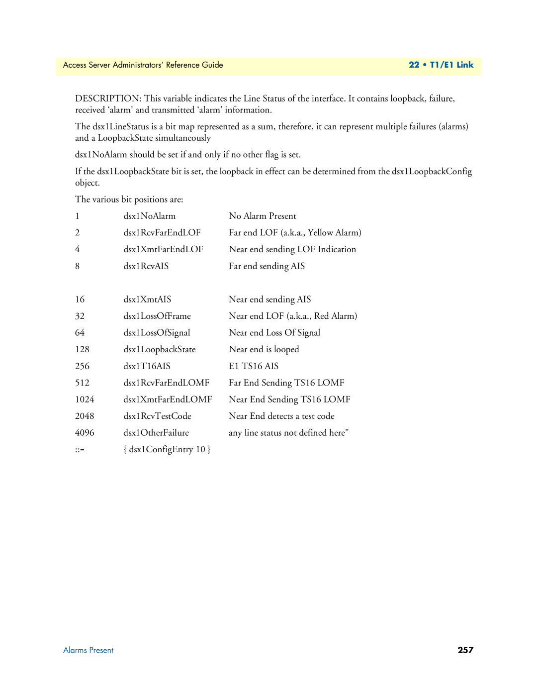
Physical Line Alarms dsx1LineStatus
Alarms Present
Far End Alarm Failure
Circuit ID dsx1CircuitIdentifier
Loss Of Signal Failure
Alarm Indication Signal AIS Failure
TS16 Alarm Indication Signal Failure
Loss Of Frame Failure
Snmp MIB definition
Isdn Signaling Alarms linkSignalStatus
E1 TS16 AIS
Valid Intervals dsx1ValidIntervals
Line Status-Configuration
Time Elapsed dsx1TimeElapsed
Circuit ID dsx1CircuitIdentifier
WAN Circuit Configuration-Modify
Line Interface Settings
Receive Equalizer linkRxEqualizer
Line Type dsx1LineType
Line Coding dsx1LineCoding
Signalling Settings
Yellow Alarm Format linkYellowFormat
Signal Mode dsx1SignalMode
Line Build Out linkLineBuildOut
Test Settings
Send Code dsx1SendCode
Loopback Config dsx1LoopbackConfig
Error Injection linkInjectError
Desired Function channelfunction
Line Status-Channel Assignment
Channel channelIndex
CurrentState ChannelState
Near End Line Statistics-Current
Severely Errored Seconds dsx1CurrentSESs
Errored Seconds dsx1CurrentESs
Severely Errored Frame Seconds dsx1CurrentSEFSs
Line Errored Seconds dsx1CurrentLESs
Near End Line Statistics-History
Near End Line Statistics-Totals
Severely Errored Frame Seconds dsx1TotalSEFSs
Severely Errored Seconds dsx1TotalSESs
Line Errored Seconds dsx1TotalLESs
Bursty ErroredSeconds dsx1TotalBESs
Far End Line Statistics-Current
Far End Line Statistics-History
Severely Errored Frame Seconds dsx1FarEndIntervalSEFSs
Severely Errored Seconds dsx1FarEndIntervalSESs
Line Errored Seconds dsx1FarEndIntervalLESs
Bursty Errored Seconds dsx1FarEndIntervalBESs
Far End Line Statistics-Totals
Using Non-Facility Associated Signaling Nfas
Bursty Errored Seconds dsx1FarEndTotalBESs
Configuring Nfas
Degraded Minutes dsx1FarEndTotalDMs
RAS hosts 1 Nfas group containing 3 PRIs
Sync PPP
Sync PPP
Line Status-Channel Assignment
WAN Circuit Configuration window
PPP Main Window
PPP configuration
Ip Mask pppServiceIpMask
Ip Address pppServiceIpAddress
Default Settings
State pppActState
Authentication Side pppDefaultAuthenticationSide
Authentication Technique pppDefaultAuthenticationTechnique
Authentication Username pppDefaultAuthenticationUsername
Authentication Password pppDefaultAuthenticationPassword
PPP Link Window
Compression pppDefaultIpCompression
Link frDlcmiIfIndex
Status framerelStatus
Link Configuration
Authentication Username pppAuthenticationUsername
Authentication Side pppAuthenticationSide
Authentication Password pppAuthenticationPassword
Security Level pppAccessLevel
Allow Magic Number Negotiation pppMagicNumber
Link Compression pppLinkCompression
Bad Address pppStatBadAddresses
Bad Controls pppStatBadControls
ACC Map pppStatLocalToPeerACCMap
LCP AuthenticationpppStatLcpAuth
Peer-Local ACC Map pppStatPeerToLocalACCMap
Local-Remote AC ComprsnpppStatLocalToRemoteACComp
Transmit Frame Check Seq. Size pppStatTransmitFcsSize
Remote-Local AC Comprsn pppStatRemoteToLocalACComp
Receive Frame Check Seq. Size pppStatReceiveFcsSize
Operational Status pppIpOperStatus
Local Max Slot ID pppIpLocalMaxSlotId
Remote Max Slot ID pppIpRemoteMaxSlotId
Octets Sent pppActSentOctets
Octets Received pppActReceivedOctets
Link Configuration
Modify Link Configuration Window
Layer 2 Tunneling Protocol L2TP
Static Authentication
L2TP Configuration
L2TP Radius Authentication
Radius Authentication
Cisco Configuration
Configuration Example
This will enable the use of tunnel authentication
Contacting Patton
About window
Patton Electronics Company contact information
License
Definitions
End User License Agreement
Title
Warranty
Term
Grant of License
Appendix a Supported Radius Attributes
Access-Request Attributes
Access-Accept Attributes
Accounting-Start Attributes
Access-Challenge Attributes
Accounting-Stop Attributes
Appendix B MIB trees
Model 2960 MIB Tree Structure
Appendix C Technical Reference
Radius Client/Server Architecture
Configuring a Radius server
What Is RADIUS?
Radius Services
Radius Standards
Radius Authentication Procedure
Radius Resources
RADIUS-Where Can I Get It?
Overview
Configuring Radius
Configuring Radius Authentication
Authentication window
Finding the Snmp Name
Using Snmp with the Access Server
Finding the branch where the Snmp parameter resides
MIB tree for Model 2960 access server
Configuring Nfas
Configuring Non-Facility Associated Signaling Nfas
Line Configuration
Configuring Frame Relay
WAN Channel Assignment main screen
Configuring PVCs
Configuring Frame Relay link parameters
Click on Submit Query
Configuring Permanent Virtual Circuits
IP routing with Frame Relay example
Configuring IP routing with a Frame Relay Link
Click Add Route
Link Status and the IP Forwarding
Setting up IP address pools by configuring Dnis Ip Pools
Configuring Dnis
Setting up a Dnis user profile
Setting up a Dnis group
Configuring the RAS
Configuring a leased line/dedicated line connection
Modem properties window
Configuring the remote end using Microsoft Windows
Under the Options tab set Redial attempts to a high number