IMPORTANT: Before con- necting the hardware, un- plug the VCR’s power cord from the wall outlet, and turn off the PC.
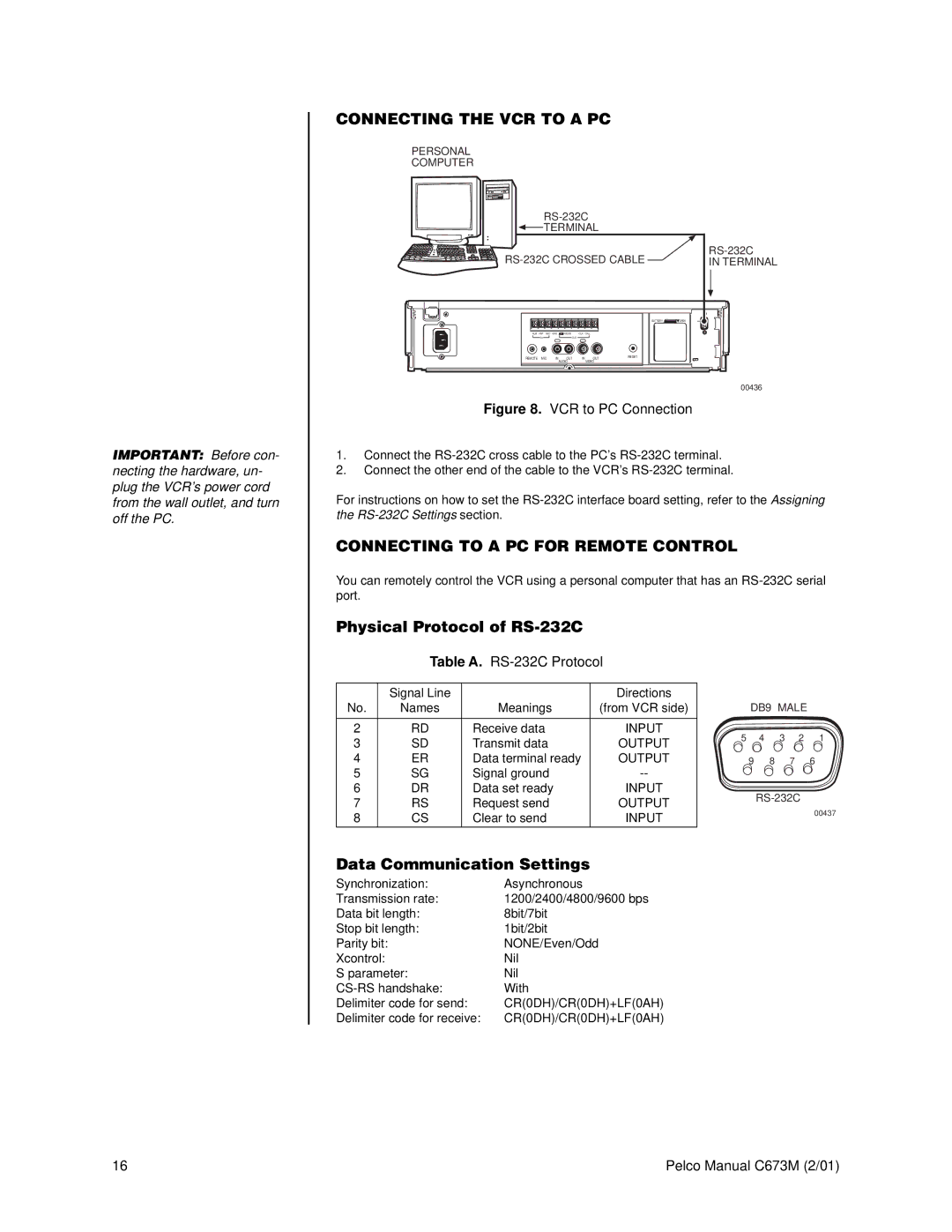
CONNECTING THE VCR TO A PC
PERSONAL
COMPUTER
|
| ||||
TERMINAL |
|
| |||
| |||||
IN TERMINAL | |||||
|
|
|
| BATTERY | OPEN |
ALM RST REC GND | MODE | CLK | CALL |
|
|
IN | OUT |
|
|
|
|
REMOTE MIC IN | OUT | IN | OUT | RESET |
|
| AUDIO |
| VIDEO |
|
|
|
|
|
|
| 00436 |
Figure 8. VCR to PC Connection
1.Connect the
2.Connect the other end of the cable to the VCR’s
For instructions on how to set the
CONNECTING TO A PC FOR REMOTE CONTROL
You can remotely control the VCR using a personal computer that has an
Physical Protocol of RS-232C
Table A. RS-232C Protocol
| Signal Line |
| Directions |
|
|
|
|
| |
No. | Names | Meanings | (from VCR side) |
| DB9 MALE |
| |||
2 | RD | Receive data | INPUT | 5 | 4 | 3 | 2 | 1 | |
3 | SD | Transmit data | OUTPUT | ||||||
|
|
|
|
| |||||
4 | ER | Data terminal ready | OUTPUT |
| 9 | 8 | 7 | 6 | |
5 | SG | Signal ground |
|
|
|
|
| ||
6 | DR | Data set ready | INPUT |
|
| ||||
7 | RS | Request send | OUTPUT |
|
| ||||
|
|
|
| 00437 | |||||
8 | CS | Clear to send | INPUT |
|
|
|
| ||
|
|
|
|
| |||||
Data Communication Settings
Synchronization: | Asynchronous |
Transmission rate: | 1200/2400/4800/9600 bps |
Data bit length: | 8bit/7bit |
Stop bit length: | 1bit/2bit |
Parity bit: | NONE/Even/Odd |
Xcontrol: | Nil |
S parameter: | Nil |
With | |
Delimiter code for send: | CR(0DH)/CR(0DH)+LF(0AH) |
Delimiter code for receive: | CR(0DH)/CR(0DH)+LF(0AH) |
16 | Pelco Manual C673M (2/01) |