MGC-25 Getting Started Guide
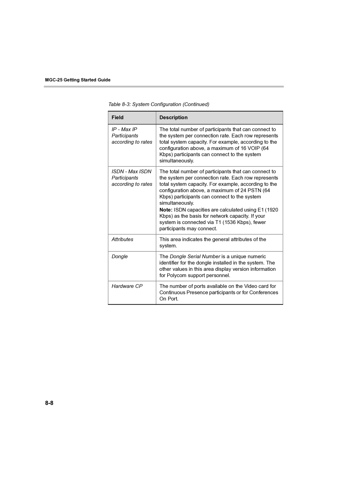
Table 8-3: System Configuration (Continued)
Field | Description |
|
|
IP - Max IP | The total number of participants that can connect to |
Participants | the system per connection rate. Each row represents |
according to rates | total system capacity. For example, according to the |
| configuration above, a maximum of 16 VOIP (64 |
| Kbps) participants can connect to the system |
| simultaneously. |
|
|
ISDN - Max ISDN | The total number of participants that can connect to |
Participants | the system per connection rate. Each row represents |
according to rates | total system capacity. For example, according to the |
| configuration above, a maximum of 24 PSTN (64 |
| Kbps) participants can connect to the system |
| simultaneously. |
| Note: ISDN capacities are calculated using E1 (1920 |
| Kbps) as the basis for network capacity. If your |
| system is connected via T1 (1536 Kbps), fewer |
| participants may connect. |
|
|
Attributes | This area indicates the general attributes of the |
| system. |
|
|
Dongle | The Dongle Serial Number is a unique numeric |
| identifier for the dongle installed in the system. The |
| other values in this area display version information |
| for Polycom support personnel. |
|
|
Hardware CP | The number of ports available on the Video card for |
| Continuous Presence participants or for Conferences |
| On Port. |
|
|