4.0 DFS - 1 SETUP
Parameter | No. | Value |
| Parameter | No. | Value |
|
|
|
|
|
|
|
Maximum Motor Speed | 6 | 1750 |
| Master Jump Up Amount | 49 | 1 |
|
|
|
|
|
|
|
High Engineering Units | 14 | 1750 |
| Master Jump Down Amount | 50 | 1 |
|
|
|
|
|
|
|
Encoder Pulses Per Rev | 7 | 120 |
| Analog Input #1 | 17 | |
|
|
|
|
|
|
|
Pulse Multiplier | 46 | x 4 |
| Analog Output #1 | 25 | Speed |
|
|
|
|
|
|
|
PWM Mode | 47 |
| Analog Output #2 | 28 | Load | |
|
|
|
|
|
|
|
Drive Gain | 42 | 128 |
| Input Debounce Value | 53 | 10 mSec |
|
|
|
|
|
|
|
Drive Stability | 43 | 128 |
| Digital Input #1 | 31 | RUN |
|
|
|
|
|
|
|
Motoring Current Limit | 44 | 100 |
| Digital Input #2 | 32 | PRESET |
|
|
|
|
|
|
|
Regenerative Current Limit | 45 | 100 |
| Digital Input #3 | 33 | UP |
|
|
|
|
|
|
|
Up/Down Function | 48 | Jump |
| Digital Input #4 | 34 | DOWN |
|
|
|
|
|
|
|
Float or Freeze Setpoint | 54 | Float |
| Digital Input #5 | 35 | REVERSE |
|
|
|
|
|
|
|
Mode of Operation | 5 | Master |
| Digital Output #1 | 38 | RUN |
|
|
|
|
|
|
|
Master Accel Rate | 8 | 10k mSec |
| Digital Output #2 | 39 | NO FAULT |
|
|
|
|
|
|
|
Master Decel Rate | 9 | 10k mSec |
| Digital Output #3 | 40 | AT SPD |
|
|
|
|
|
|
|
Master Preset Speed | 12 | 200 |
| Digital Output #4 | 41 | REMOTE |
|
|
|
|
|
|
|
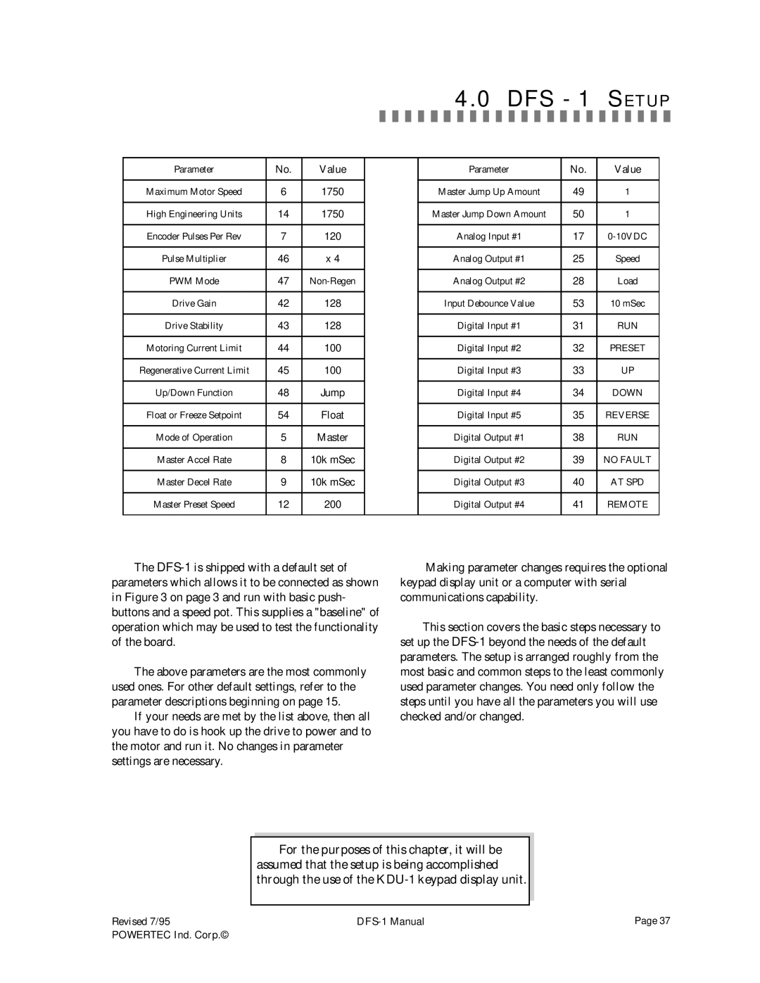
The
The above parameters are the most commonly used ones. For other default settings, refer to the parameter descriptions beginning on page 15.
If your needs are met by the list above, then all you have to do is hook up the drive to power and to the motor and run it. No changes in parameter settings are necessary.
Making parameter changes requires the optional keypad display unit or a computer with serial communications capability.
This section covers the basic steps necessary to set up the
For the purposes of this chapter, it will be assumed that the setup is being accomplished through the use of the
Revised 7/95 | Page 37 | |
POWERTEC Ind. Corp.© |
|
|