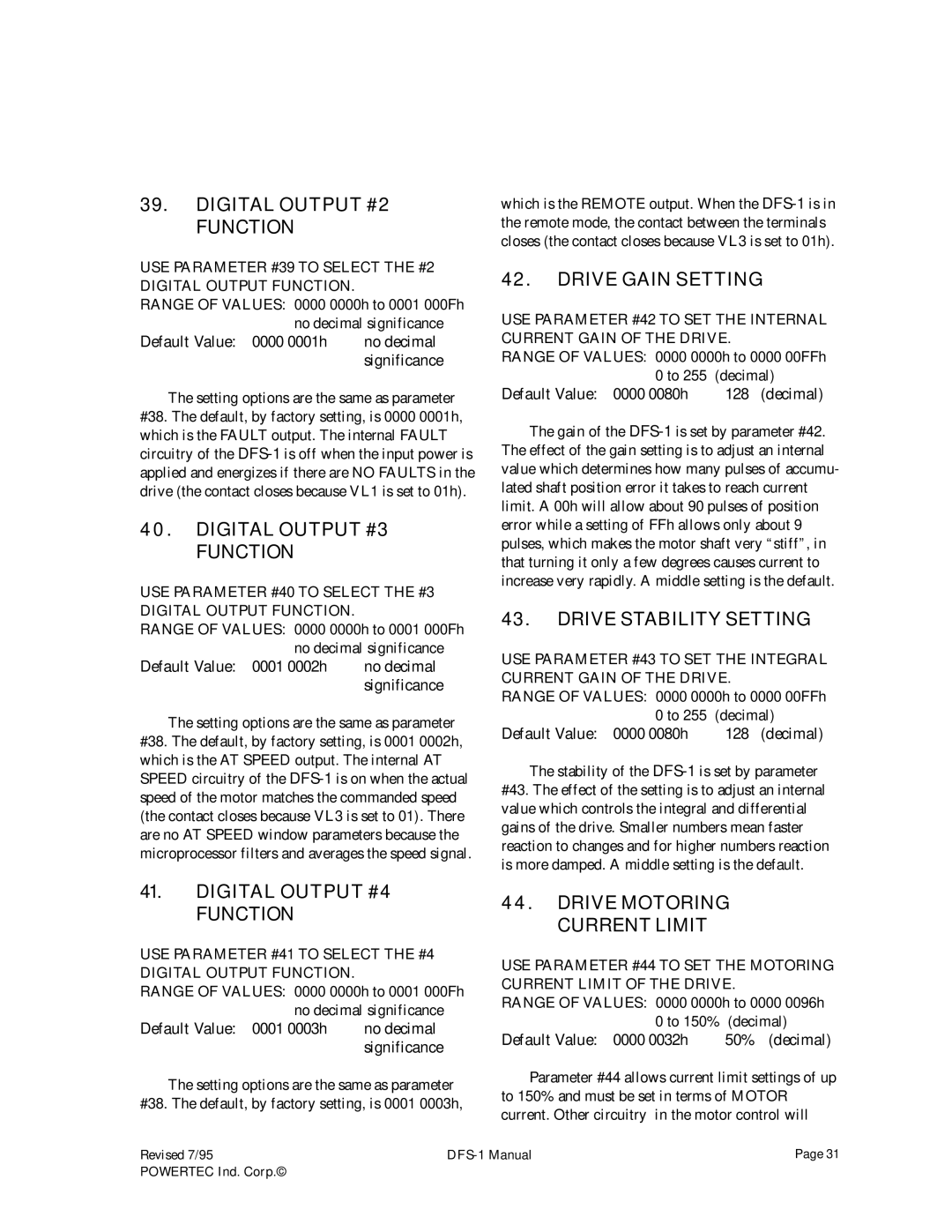
39.DIGITAL OUTPUT #2 FUNCTION
USE PARAMETER #39 TO SELECT THE #2 DIGITAL OUTPUT FUNCTION.
RANGE OF VALUES: 0000 0000h to 0001 000Fh no decimal significance
Default Value: 0000 0001h no decimal significance
The setting options are the same as parameter #38. The default, by factory setting, is 0000 0001h, which is the FAULT output. The internal FAULT circuitry of the
40.DIGITAL OUTPUT #3 FUNCTION
USE PARAMETER #40 TO SELECT THE #3 DIGITAL OUTPUT FUNCTION.
RANGE OF VALUES: 0000 0000h to 0001 000Fh no decimal significance
Default Value: 0001 0002h no decimal significance
The setting options are the same as parameter #38. The default, by factory setting, is 0001 0002h, which is the AT SPEED output. The internal AT SPEED circuitry of the
41.DIGITAL OUTPUT #4 FUNCTION
USE PARAMETER #41 TO SELECT THE #4 DIGITAL OUTPUT FUNCTION.
RANGE OF VALUES: 0000 0000h to 0001 000Fh no decimal significance
Default Value: 0001 0003h no decimal significance
The setting options are the same as parameter #38. The default, by factory setting, is 0001 0003h,
which is the REMOTE output. When the
42.DRIVE GAIN SETTING
USE PARAMETER #42 TO SET THE INTERNAL CURRENT GAIN OF THE DRIVE.
RANGE OF VALUES: 0000 0000h to 0000 00FFh
0 to 255 | (decimal) |
Default Value: 0000 0080h | 128 (decimal) |
The gain of the
43.DRIVE STABILITY SETTING
USE PARAMETER #43 TO SET THE INTEGRAL CURRENT GAIN OF THE DRIVE.
RANGE OF VALUES: 0000 0000h to 0000 00FFh
0 to 255 | (decimal) |
Default Value: 0000 0080h | 128 (decimal) |
The stability of the
44.DRIVE MOTORING CURRENT LIMIT
USE PARAMETER #44 TO SET THE MOTORING CURRENT LIMIT OF THE DRIVE.
RANGE OF VALUES: 0000 0000h to 0000 0096h 0 to 150% (decimal)
Default Value: 0000 0032h | 50% (decimal) |
Parameter #44 allows current limit settings of up to 150% and must be set in terms of MOTOR current. Other circuitry in the motor control will
Revised 7/95 | Page 31 | |
POWERTEC Ind. Corp.© |
|
|
