PowerTec DFS-1 manual Digital Outputs, Communications, Digital Out #4 Reverse

Models: DFS-1

1 84
Download 84 pages 52.2 Kb
Page 16
Image 16

The programmable inputs (TB2-A4 through TB2-A10) may be programmed for jog, thread, or other preset speeds. The inputs may also be used to change torque levels, trim values, or ramp rates. Any value which can be affected by a parameter can be changed by a digital input.

DIGITAL OUTPUTS:

Digital outputs are located on TB2:B. The four outputs are normally open relay contacts. The contacts are rated at 120VAC at 1 amp, resistive.

The default setup assigns the outputs as follows:

Digital Out #1

Run

Digital Out #2

No Fault

Digital Out #3

At Speed

Digital Out #4

Reverse

These assignments may be changed by parameters. All of the digital outputs are programmable and

may be configured as Normally Open or Normally Closed. If more than one contact is required for a certain function, an external relay may be used, or more than one output may be programmed for the same function.

COMMUNICATIONS:

The standard communications for the DFS-1 is the EIA standard RS-485 communications format over a single twisted pair cable into TB3:A terminals 1 and 2. Terminal 3 is for the shield. DO NOT CONNECT TERMINAL 3 TO GROUND! Maxi- mum allowable distance for twisted pair operation is 4000 meters (about 12,000 feet). Maximum nodes without repeaters is 32. Maximum communications rate is 38.4 kilobaud. The last unit on the comm line should have a jumper at JP2 on the rightmost 2 pins. All other units should have the jumper on the leftmost two pins.

There is an RS-485 local programming input at TB3:B for an optional keypad display unit.

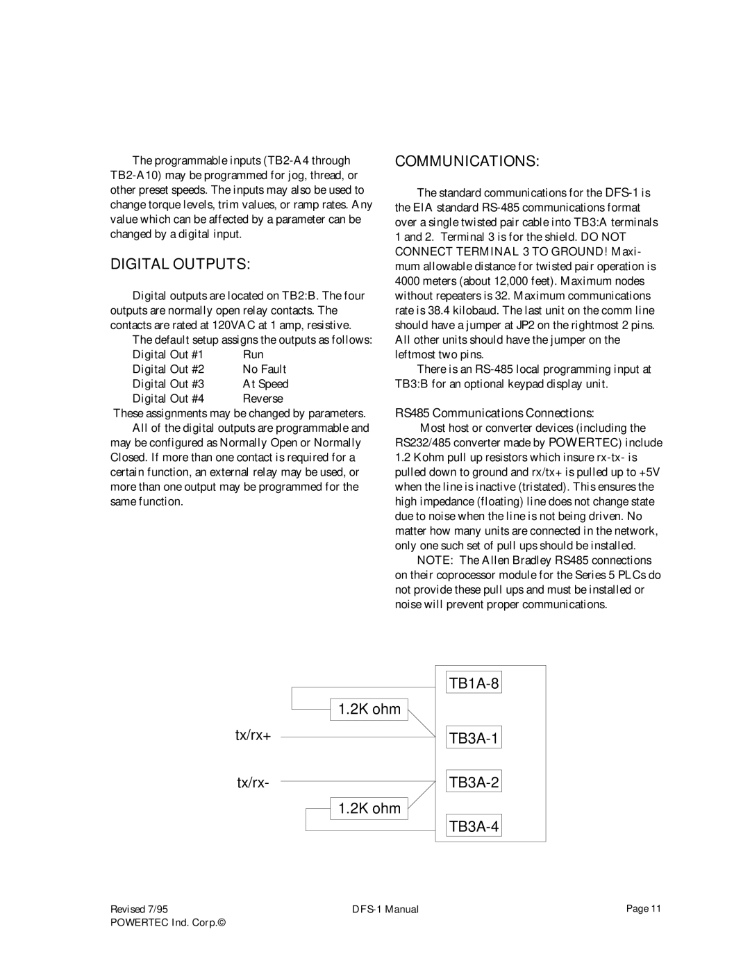
RS485 Communications Connections:

Most host or converter devices (including the RS232/485 converter made by POWERTEC) include

1.2Kohm pull up resistors which insure rx-tx- is pulled down to ground and rx/tx+ is pulled up to +5V when the line is inactive (tristated). This ensures the high impedance (floating) line does not change state due to noise when the line is not being driven. No matter how many units are connected in the network, only one such set of pull ups should be installed.

NOTE: The Allen Bradley RS485 connections on their coprocessor module for the Series 5 PLCs do not provide these pull ups and must be installed or noise will prevent proper communications.

1.2K ohm

tx/rx+

tx/rx-

1.2K ohm

TB1A-8

TB3A-1

TB3A-2

TB3A-4

Revised 7/95

DFS-1 Manual

Page 11

POWERTEC Ind. Corp.©


Page 16
Image 16
PowerTec DFS-1 manual Digital Outputs, Communications, Digital Out #4 Reverse