The default speed reference input is Analog Input #1, located on TB1:B. The default input is for a 0 to +10VDC for zero to full speed of the motor. Terminal 3 is the positive side of the input and terminal 4 is the negative side. If the speed signal being used is externally supplied, the differential input will have a noise cancelling effect. Terminal 1 on TB1:B is a common for shields.
Reference sources of +10VDC and
IN THE DEFAULT SETUP, ONLY ANALOG INPUT #1 IS ACTIVE. WHILE THE OTHER ANALOG INPUT HAS A DEFAULT SETUP, IT IS NOT ACTIVE UNTIL THE USER CHANGES THE SETUP TO MAKE IT ACTIVE.
The microprocessor will look ONLY to Analog Input #1 for speed information until it is told to do otherwise in the setup program.
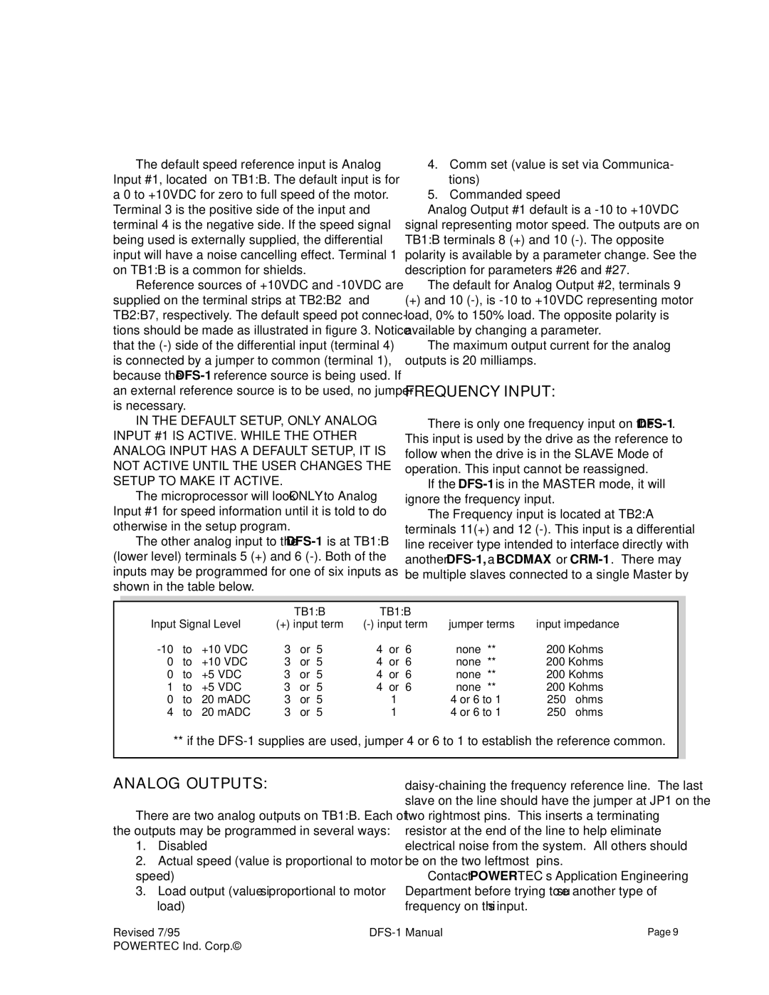
The other analog input to the
4.Comm set (value is set via Communica- tions)
5.Commanded speed
Analog Output #1 default is a
The default for Analog Output #2, terminals 9
(+)and 10
The maximum output current for the analog outputs is 20 milliamps.
FREQUENCYINPUT:
There is only one frequency input on the
If the
The Frequency input is located at TB2:A terminals 11(+) and 12
|
|
|
| TB1:B | TB1:B |
|
|
| |
Input Signal Level | (+) input term | jumper terms | input impedance | ||||||
to | +10 VDC | 3 | or 5 | 4 | or 6 | none ** | 200 Kohms | ||
0 | to | +10 VDC | 3 | or 5 | 4 | or 6 | none ** | 200 Kohms | |
0 | to | +5 VDC | 3 | or 5 | 4 | or 6 | none ** | 200 Kohms | |
1 | to | +5 VDC | 3 | or 5 | 4 | or 6 | none ** | 200 Kohms | |
0 | to | 20 mADC | 3 | or 5 |
| 1 | 4 or 6 to 1 | 250 | ohms |
4 | to | 20 mADC | 3 | or 5 |
| 1 | 4 or 6 to 1 | 250 | ohms |
** if the
ANALOG OUTPUTS:
There are two analog outputs on TB1:B. Each of the outputs may be programmed in several ways:
1.Disabled
2.Actual speed (value is proportional to motor speed)
3.Load output (value is proportional to motor load)
Contact POWERTEC’s Application Engineering Department before trying to use another type of frequency on this input.
Revised 7/95 | Page 9 | |
POWERTEC Ind. Corp.© |
|
|