FREQUENCYOUTPUT:DIGITAL INPUTS:
There are two outputs available to supply a frequency for external use.
The first is located at TB2:B terminal 10 (+) and 11
areference frequency input for another
When operating the DFS as a slave, the output frequency is internally divided by 16 in addition to being multiplied by the set ratio from the slave. As a consequence, the frequency output from a DFS slave cannot be used as the reference to another DFS slave without some way of first multiplying this frequency by 16. POWERTEC’s Cascade Ratio Multiplier option board
The other frequency output is at TB2:B13. This is a 24VDC peak square wave referenced to the DFS- 1 common (TB2:B14). This signal is at the motor speed output reference frequency and may be used to interface with a DIGIMAX or a BLDC motor control. This output sources a maximum of 10mA and can sink 30mA.
There are eight digital control inputs on TB2:A as well as a +24VDC supply
The functions of all inputs are programmable except Emergency Stop
The default parameter setup is for a set of standard motor controller input connections on TB2:A terminal strip (see figure 3 on page 3).
Five of the inputs are set up for standard push- button operation of the
Run | 4 (+) |
Preset | 5 (+) |
UP (increase) | 6 (+) |
DOWN (decrease) | 7 (+) |
Reverse | 8 (+) |
All of these inputs are referred to
Each of these inputs will take a +24VDC input (no more than 30VDC, not less than 18VDC). If an external source of +24VDC is used,
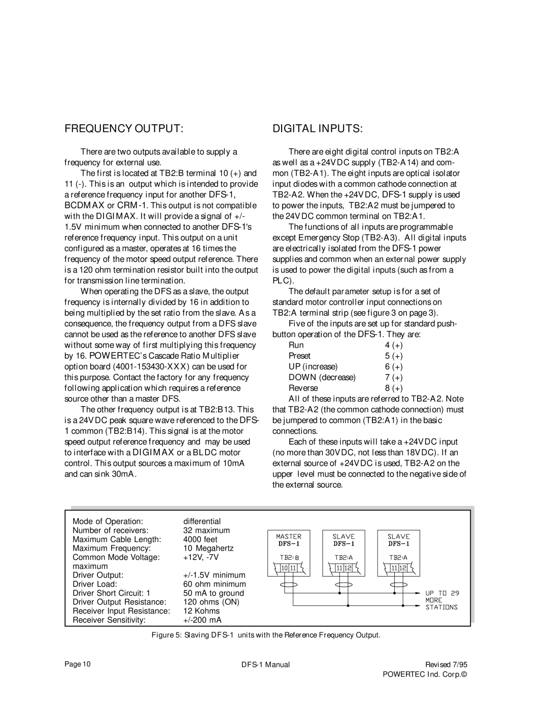
Mode of Operation: | differential |
Number of receivers: | 32 maximum |
Maximum Cable Length: | 4000 feet |
Maximum Frequency: | 10 Megahertz |
Common Mode Voltage: | +12V, |
maximum |
|
Driver Output: | |
Driver Load: | 60 ohm minimum |
Driver Short Circuit: 1 | 50 mA to ground |
Driver Output Resistance: | 120 ohms (ON) |
Receiver Input Resistance: | 12 Kohms |
Receiver Sensitivity: |
B |
Figure 5: Slaving DFS-1 units with the Reference Frequency Output.
Page 10 |
| Revised 7/95 |
|
| POWERTEC Ind. Corp.© |