4 – Hardware Installation Hardware Installation
S
4.Remove the cover screws and cover plate to expose the system’s motherboard. For specific instructions on how to do this, follow the hardware documentation that came with your system.
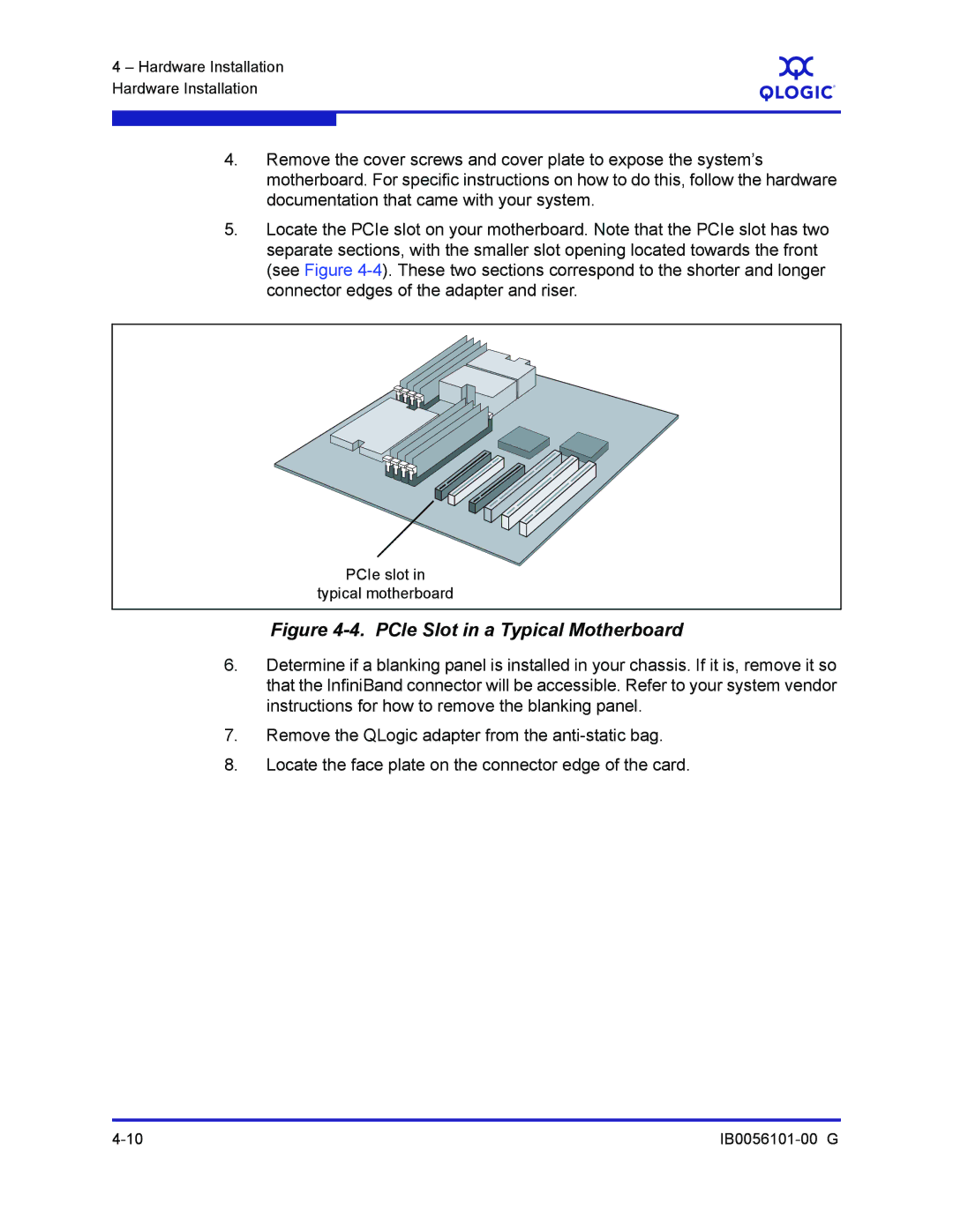
5.Locate the PCIe slot on your motherboard. Note that the PCIe slot has two separate sections, with the smaller slot opening located towards the front (see Figure
PCIe slot in
typical motherboard
Figure 4-4. PCIe Slot in a Typical Motherboard
6.Determine if a blanking panel is installed in your chassis. If it is, remove it so that the InfiniBand connector will be accessible. Refer to your system vendor instructions for how to remove the blanking panel.
7.Remove the QLogic adapter from the
8.Locate the face plate on the connector edge of the card.