4 – Hardware Installation Hardware Installation
S
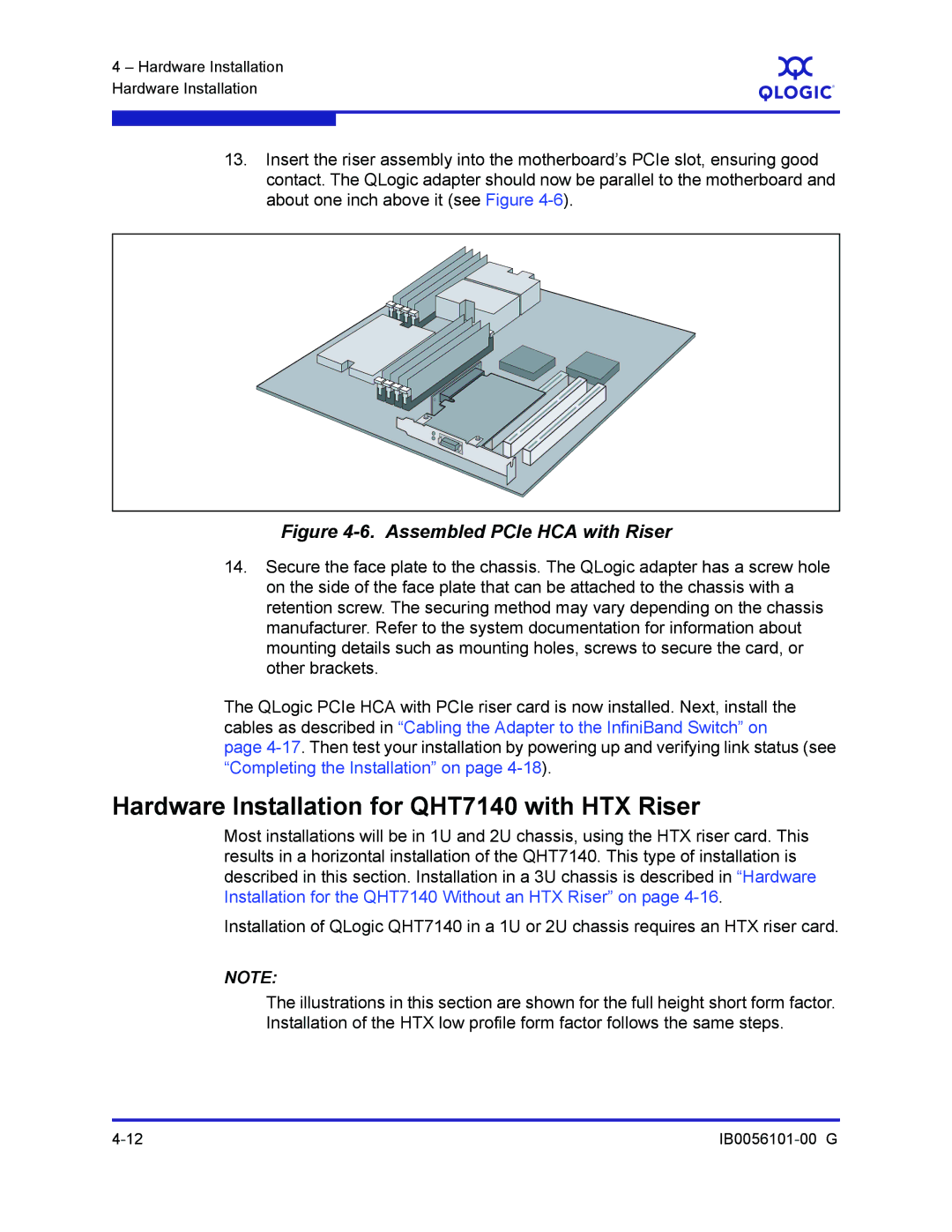
13.Insert the riser assembly into the motherboard’s PCIe slot, ensuring good contact. The QLogic adapter should now be parallel to the motherboard and about one inch above it (see Figure
Figure 4-6. Assembled PCIe HCA with Riser
14.Secure the face plate to the chassis. The QLogic adapter has a screw hole on the side of the face plate that can be attached to the chassis with a retention screw. The securing method may vary depending on the chassis manufacturer. Refer to the system documentation for information about mounting details such as mounting holes, screws to secure the card, or other brackets.
The QLogic PCIe HCA with PCIe riser card is now installed. Next, install the cables as described in “Cabling the Adapter to the InfiniBand Switch” on
page
Hardware Installation for QHT7140 with HTX Riser
Most installations will be in 1U and 2U chassis, using the HTX riser card. This results in a horizontal installation of the QHT7140. This type of installation is described in this section. Installation in a 3U chassis is described in “Hardware Installation for the QHT7140 Without an HTX Riser” on page
Installation of QLogic QHT7140 in a 1U or 2U chassis requires an HTX riser card.
NOTE:
The illustrations in this section are shown for the full height short form factor. Installation of the HTX low profile form factor follows the same steps.