A
4 – Hardware Installation Hardware Installation
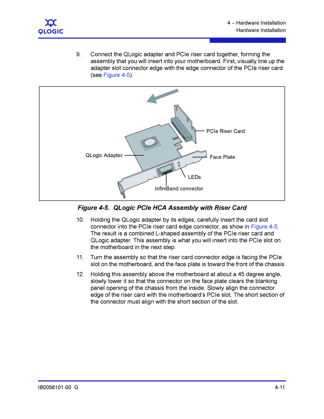
9.Connect the QLogic adapter and PCIe riser card together, forming the assembly that you will insert into your motherboard. First, visually line up the adapter slot connector edge with the edge connector of the PCIe riser card (see Figure
.
PCIe Riser Card
QLogic Adapter | Face Plate |
|
![]() LEDs
LEDs
InfiniBand connector
Figure 4-5. QLogic PCIe HCA Assembly with Riser Card
10.Holding the QLogic adapter by its edges, carefully insert the card slot connector into the PCIe riser card edge connector, as show in Figure
11.Turn the assembly so that the riser card connector edge is facing the PCIe slot on the motherboard, and the face plate is toward the front of the chassis.
12.Holding this assembly above the motherboard at about a 45 degree angle, slowly lower it so that the connector on the face plate clears the blanking panel opening of the chassis from the inside. Slowly align the connector edge of the riser card with the motherboard’s PCIe slot. The short section of the connector must align with the short section of the slot.