A
4 – Hardware Installation Hardware Installation
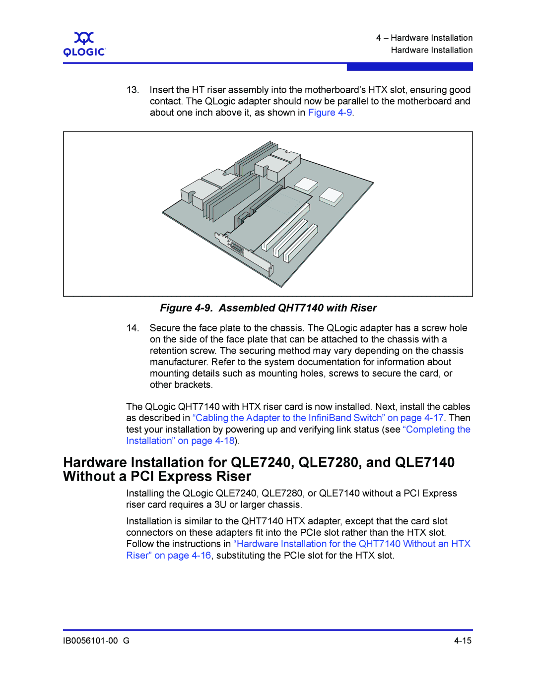
13.Insert the HT riser assembly into the motherboard’s HTX slot, ensuring good contact. The QLogic adapter should now be parallel to the motherboard and about one inch above it, as shown in Figure
Figure 4-9. Assembled QHT7140 with Riser
14.Secure the face plate to the chassis. The QLogic adapter has a screw hole on the side of the face plate that can be attached to the chassis with a retention screw. The securing method may vary depending on the chassis manufacturer. Refer to the system documentation for information about mounting details such as mounting holes, screws to secure the card, or other brackets.
The QLogic QHT7140 with HTX riser card is now installed. Next, install the cables as described in “Cabling the Adapter to the InfiniBand Switch” on page
Hardware Installation for QLE7240, QLE7280, and QLE7140 Without a PCI Express Riser
Installing the QLogic QLE7240, QLE7280, or QLE7140 without a PCI Express riser card requires a 3U or larger chassis.
Installation is similar to the QHT7140 HTX adapter, except that the card slot connectors on these adapters fit into the PCIe slot rather than the HTX slot. Follow the instructions in “Hardware Installation for the QHT7140 Without an HTX Riser” on page