Appendix Ⅰ(Reference for circuit diagnostics)
Ref. 3) Check a load
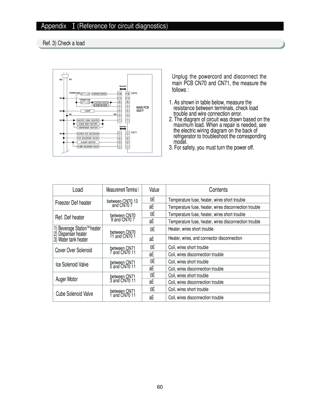
Unplug the powercord and disconnect the
main PCB CN70 and CN71, the measure the
follows :
1.As shown in table below, measure the resistance between terminals, check load trouble and wire connection error.
2.The diagram of circuit was drawn based on the maximum load. When a repair is needed, see the electric wiring diagram on the back of refrigerator to troubleshoot the corresponding model.
3.For safety, you must turn the power off.
Load | Measurement Termina l | Value | Contents | |
|
|
|
| |
Freezer Def heater | between CN70 13 | 0Ω | Temperature fuse, heater, wires short trouble | |
|
| |||
| and CN70 7 | ∞Ω | Temperature fuse, heater, wires disconnection trouble | |
|
| |||
Ref. Def heater | between CN70 | 0Ω | Temperature fuse, heater, wires short trouble | |
|
| |||
| 9 and CN70 7 | ∞Ω | Temperature fuse, heater, wires disconnection trouble | |
|
| |||
1) Beverage StationTM heater | between CN70 | 0Ω | Heater, wires short trouble | |
2) Dispenser heater |
|
| ||
|
| |||
3) Water tank heater | 11 and CN70 1 | ∞Ω | Heater, wires, and connector disconnection | |
| ||||
Cover Over Solenoid | between CN71 | 0Ω | Coil, wires short trouble | |
|
| |||
| 7 and CN70 11 | ∞Ω | Coil, wires disconnection trouble | |
|
| |||
Ice Solenoid Valve | between CN71 | 0Ω | Coil, wires short trouble | |
5 and CN70 11 | ∞Ω | Coil, wires disconnection trouble | ||
| ||||
|
| |||
Auger Motor | between CN71 | 0Ω | Coil, wires short trouble | |
3 and CN70 11 | ∞Ω | Coil, wires disconnection trouble | ||
| ||||
Cube Solenoid Valve | between CN71 | 0Ω | Coil, wires short trouble | |
1 and CN70 11 | ∞Ω | Coil, wires disconnection trouble | ||
|
| |||
|
|
|
|
60