installation and external connection
EARTH-GROUNDING THE COMMUNICATION CABLES
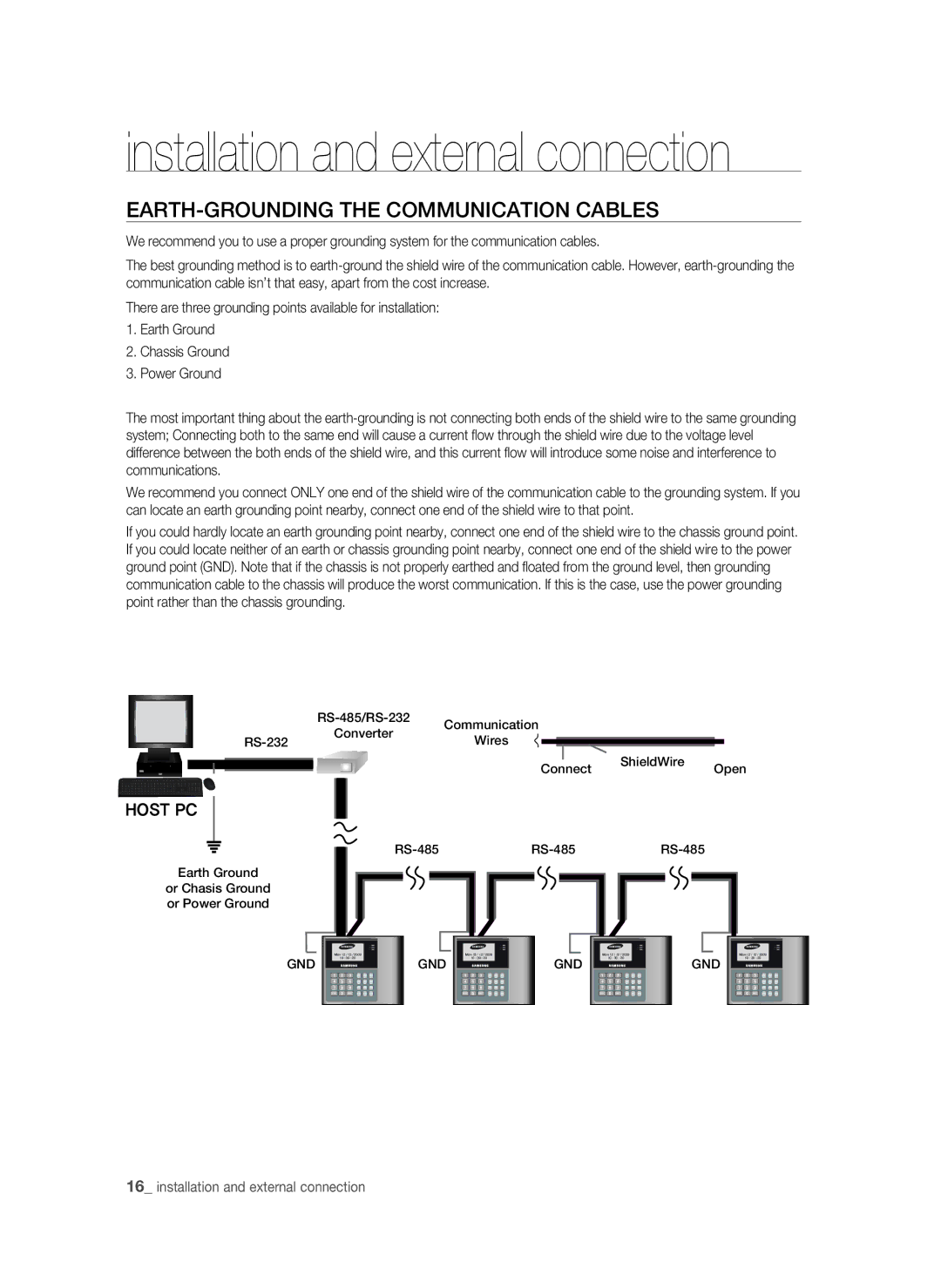
We recommend you to use a proper grounding system for the communication cables.
The best grounding method is to
There are three grounding points available for installation:
1.Earth Ground
2.Chassis Ground
3.Power Ground
The most important thing about the
We recommend you connect ONLY one end of the shield wire of the communication cable to the grounding system. If you can locate an earth grounding point nearby, connect one end of the shield wire to that point.
If you could hardly locate an earth grounding point nearby, connect one end of the shield wire to the chassis ground point. If you could locate neither of an earth or chassis grounding point nearby, connect one end of the shield wire to the power ground point (GND). Note that if the chassis is not properly earthed and floated from the ground level, then grounding communication cable to the chassis will produce the worst communication. If this is the case, use the power grounding point rather than the chassis grounding.
| Communication | ||
| Converter | ||
Wires | |||
|
ShieldWire
ConnectOpen
HOST PC
Earth Ground
or Chasis Ground or Power Ground
|
|
|
|
|
|
|
|
|
|
|
|
|
|
|
|
|
|
|
|
| |||
Mon 12 / 12 / 2009 |
| Mon 12 / 12 / 2009 |
| Mon 12 / 12 / 2009 |
| Mon 12 / 12 / 2009 |
| ||||||||||||||||
GND | 10 : 30 : 20 |
|
|
| GND | 10 : 30 : 20 |
|
|
| GND | 10 : 30 : 20 |
|
|
| GND | 10 : 30 : 20 |
|
|
| ||||
|
|
|
|
|
|
|
|
|
|
|
|
|
|
|
|
|
|
|
| ||||
1 | 2 | 3 | F1 | F2 | F3 | 1 | 2 | 3 | F1 | F2 | F3 | 1 | 2 | 3 | F1 | F2 | F3 | 1 | 2 | 3 | F1 | F2 | F3 |
4 | 5 | 6 | F4 | F5 | F6 | 4 | 5 | 6 | F4 | F5 | F6 | 4 | 5 | 6 | F4 | F5 | F6 | 4 | 5 | 6 | F4 | F5 | F6 |
7 | 8 | 9 | F7 | F8 | F9 | 7 | 8 | 9 | F7 | F8 | F9 | 7 | 8 | 9 | F7 | F8 | F9 | 7 | 8 | 9 | F7 | F8 | F9 |
ESC | 0 | ENT | F10 | F11 F12 | ESC | 0 | ENT | F10 | F11 F12 | ESC | 0 | ENT | F10 | F11 F12 | ESC | 0 | ENT | F10 | F11 F12 | ||||
16_ installation and external connection
