installation and external connection
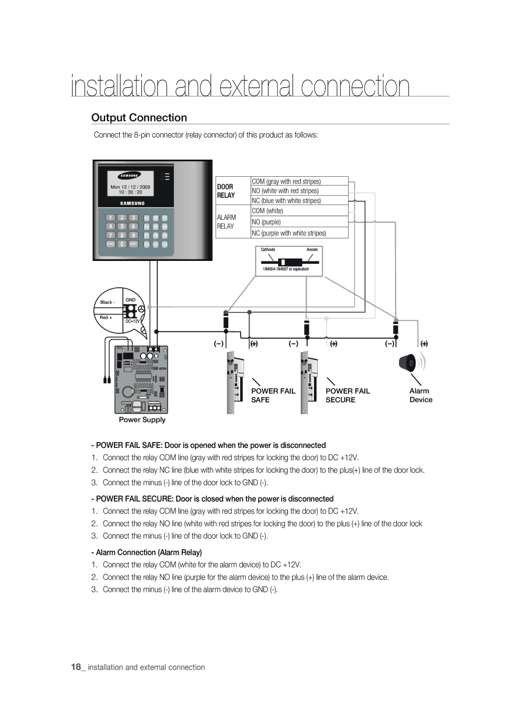
Output Connection
Connect the
183
%003
Mon 12 / 12 / 2009
10 : 30 : 20
1 2 3 F1 F2 F3
4 5 6 F4 F5 F6
7 8 9 F7 F8 F9
ESC 0 ENT F10 F11 F12
Black - GND
Red +
DC+12V
Power Supply
DOOR | COM (gray with red stripes) |
|
| ||
NO (white with red stripes) |
| |
RELAY |
| |
NC (blue with white stripes) |
| |
|
| |
ALARM | COM (white) |
|
| ||
NO (purple) |
| |
RELAY |
| |
NC (purple with white stripes) |
| |
|
|
Cathode | Anode |
|
|
|
|
|
|
|
|
|
|
|
|
|
|
|
|
| |
POWER FAIL | POWER FAIL | Alarm |
SAFE | SECURE | Device |
- POWER FAIL SAFE: Door is opened when the power is disconnected
1.Connect the relay COM line (gray with red stripes for locking the door) to DC +12V.
2.Connect the relay NC line (blue with white stripes for locking the door) to the plus(+) line of the door lock.
3.Connect the minus
- POWER FAIL SECURE: Door is closed when the power is disconnected
1.Connect the relay COM line (gray with red stripes for locking the door) to DC +12V.
2.Connect the relay NO line (white with red stripes for locking the door) to the plus (+) line of the door lock
3.Connect the minus
- Alarm Connection (Alarm Relay)
1.Connect the relay COM (white for the alarm device) to DC +12V.
2.Connect the relay NO line (purple for the alarm device) to the plus (+) line of the alarm device.
3.Connect the minus
18_ installation and external connection