DC Inverter MULTI-SYSTEM AIR Conditioner
RoHS
For safe installation and trouble-free operation, you must
Please Read Before Starting
Table of Contents
Installation Instructions Appendix a
Applicable Indoor Units
Indoor Unit SAP-KRV96EHDSA, SAP-KRV126EHDS
C D.B. When combined with SAP-KRV186EH or SAP-KRV246EH
Outdoor Unit SAP-CMRV1426EH, SAP-CMRV1926EH, SAP-CMRV1936EH
Unit Specifications
Outdoor Unit
Indoor Unit
SAP-KMRV96EH ⋅
SAP-CMRV1926EH
SAP-KMRV96EH ⋅ 1 + SAP-KRV186EH ⋅
SAP-CMRV1936EH
SAP-CMRV2446EH
SAP-CMRV3146EH
Outdoor Unit SAP-CMRV1426EH
Major Component Specifications
Outdoor Unit
Outdoor Unit SAP-CMRV1926EH
Outdoor Unit SAP-CMRV1936EH
Outdoor Unit SAP-CMRV2446EH
Outdoor Unit SAP-CMRV3146EH
Other Component Specifications
Temperature C
Dimensional Data
ID23
Unit mm 852-0-0010-13400-0
Unit mm 852-0-0010-10900-0
Unit mm 852-0-0010-11000-0
Unit mm 852-0-0010-11100-0
Outdoor Unit SAP-CMRV1426EH Indoor unit Outdoor unit
Refrigerant Flow Diagram
Insulation of Refrigerant Tubing
Outdoor Unit SAP-CMRV1926EH Indoor unit Outdoor unit
Outdoor Unit SAP-CMRV1936EH Indoor unit Outdoor unit
Outdoor Unit SAP-CMRV2446EH Indoor unit Outdoor unit
Outdoor Unit SAP-CMRV3146EH Indoor unit Outdoor unit
Temperature Charts
Temperature Charts SAP-CMRV1426EH
Operating current performance chart
Indoor discharge air performance chart
Low pressure performance chart
Outdoor Unit SAP-CMRV1426EH Indoor Unit SAP-KMRV96EH ⋅
Outdoor Unit SAP-CMRV1426EHIndoor Unit
Outdoor Unit SAP-CMRV1426EH Indoor Unit SAP-KRV96EHDSA ⋅
SAP-KRV126EHDS ⋅
Temperature Charts SAP-CMRV1926EH
Outdoor Unit SAP-CMRV1926EH Indoor Unit SAP-KMRV76EH ⋅
24C Outdoor air temperature C Airtemp Indoor 20C
Outdoor Unit SAP-CMRV1926EHIndoor Unit
30C
Outdoor Unit SAP-CMRV1926EHIndoor Unit SAP-KRV186EH ⋅
SAP-KRV96EHDSA ⋅
Air Indoor Airtemp Discharge 24C Outdoor air temperature C
Temperature Charts SAP-CMRV1936EH
Outdoor Unit SAP-CMRV1936EHIndoor Unit
Indoor 27C
Tube service valve MPaG kgf/cm 2G 40.8 35.7 Atwide
Outdoor Unit SAP-CMRV1936EH Indoor Unit SAP-KRV186EH ⋅
12.2 30.6 Pressure 11.2 25.5
SAP-KRV126EHDS ⋅
Temperature Charts SAP-CMRV2446EH
Outdoor Unit SAP-CMRV2446EHIndoor Unit
SAP-KMRV96EH ⋅
SAP-KMRV126EH ⋅
Outdoor Unit SAP-CMRV2446EH Indoor Unit SAP-KRV186EH ⋅
Outdoor Unit SAP-CMRV2446EH Indoor Unit SAP-KRV246EH ⋅
Indoor Airtemp 17C Outdoor air temperature C
SAP-KRV126EHDS ⋅
Temperature Charts SAP-CMRV3146EH
Outdoor Unit SAP-CMRV3146EHIndoor Unit
Current a Operating Outdoor air temperature C
Temp Air Indoor 20C
Outdoor Unit SAP-CMRV3146EHIndoor Unit SAP-KRV186EH ⋅
Outdoor Unit SAP-CMRV3146EHIndoor Unit SAP-KRV246EH ⋅
SAP-KRV96EHDSA ⋅
SAP-KRV126EHDS ⋅
Electric Wiring Diagrams
8FA2-5257-56900-2
Unit GND
Supply Unit Inddor to
BRN GRY ORG YEL RED
Terminal Plate Supply Power GND Unit Inddor to
Functions
Explanation of Functions
Temperature of releasing
Cool
Fluctuation fan
DRY
Clean defrost
Protective Functions
Defrost Detection and Release
Non-stop defrosting
Current Control
Description of function
Automatic frequency control
Current control
Compressor Temperature Control
Reset conditions
Low Start Current
Control at Heat Start-up
Troubleshooting
Precautions before Performing Inspection or Repair
Display of the Error Monitor Lamps
Trouble Diagnosis by Error Monitor Lamps
Location of the Error Monitor Lamps
Work procedure Check items unit operation
Checking the Outdoor System
Checking the outdoor unit
Checking the defrost operation
Problems of Each Part and Inspection Points
Trouble Diagnosis of Each Part
Inspection Points for Each Part
Refrigerant gas pressure
Branch tubing temperature sensor
Breaker
Diagnostic procedure
Diagnostic results
Remedy for symptom 3 to
Trouble Diagnosis of Fan Motor
Characteristics of New Refrigerant R410A
Checklist before Servicing
What is New Refrigerant R410A?
Characteristics
Tubing precautions
No addition of compressor oil for R410A
No use of refrigerant other than R410A
If refrigerant R410A is exposed to fire
Tubing Installation Procedures
Tools Specifically for R410A
Procedure for Replacing Compressor
Case of Compressor Malfunction
Never charge a large amount
Unit. This may cause
Damage to the compressor
Example
Recharging
Case Refrigerant is Leaking
Welding leaking points
When Tubes are Extended
Charging Additional Refrigerant
Retro-Fitting Existing Systems
Use of Existing Units
Appendix a Installation Instructions SAP-CMRV1426EH
Contents
For Outdoor Unit
For safe installation and trouble-free operation, you must
…In a Ceiling or Wall
…In a Room
…In Moist or Uneven Locations
Tools Required for Installation not supplied
Accessories Supplied with Unit Table
General
Optional Copper Tubing Kit
Installation Site Selection
Additional Materials Required for Installation
Unit mm
Connecting Indoor Units
Connecting indoor unit for SAP-CMRV1426
Where snow will not blow into it
Install in a location where at least two sides are
Space is ensured for maintenance to be carried out
Decreased service life. c
Outer Dimensions of Outdoor Unit
Never install only a single indoor unit
Use of the Flaring Method
Installation Process
Flaring Procedure with a Flare Tool
Tubing Connections
Tube Dia Tightening Torque
Tubing and electric wiring
Finishing the Installation
Be sure to match refrigerant
Units
Air Purging
Air Purging with a Vacuum Pump for Test Run
Be sure to completely insert
Hex wrench before
If a CFC gas detector is used
Use a special detector for HFC
What is pump-down?
Pump-down procedure
Pump Down
If pump-down is not possible
Recommended Wire Length and Diameter
Wiring Instructions
General Precautions on Wiring
Outdoor Unit
Fore, be sure all wiring is
How to connect wiring to the terminal For Indoor Unit
For Outdoor Unit For solid core wiring or F-cable
For stranded wiring
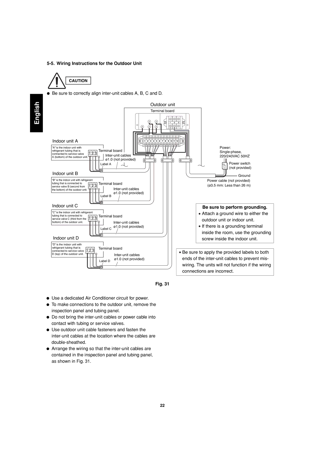
Wiring Instructions for the Outdoor Unit
Be sure to perform grounding
Performing a test run
Checking tubing and wiring
Test Run
Connecting a Home Automation Device
Installation Check Sheet
Electric Wiring Diagram
Indoor Unit SAP-KMRV74/94/124EH
SAP-KMRV76/96/126EH
Controller
II-852-6-4190-442-00-2
Deutsch Italiano Português EÏÏËÓÈο
Install the outdoor unit on a raised platform that is
Higher than drifting snow. Provide snow vents
C D
L1+L2+L3+L4 from the outdoor unit as detailed
H1, H2, H3, H4 above or below the outdoor unit
Within a total tubing length L1+L2, L1+L2+L3
Connecting indoor unit for SAP-CMRV1926
H1, H2, H3, H4
Connecting indoor unit for SAP-CMRV1936
Connecting indoor unit for SAP-CMRV2446
Outdoor unit Indoor unit
Connecting indoor unit for SAP-CMRV3146
Ø12.70 Ø6.35 Ø15.88
Install in a location where at least two sides are unob
Structed, so that the flow of air at the intake port or
Exhaust port is not blocked, and so that sufficient
Block, 15 ⋅ 40 cm beams or equal, a minimum
SAP-CMRV1926
SAP-CMRV1936
SAP-CMRV2446
SAP-CMRV3146
Indoor unit D Indoor unit C Indoor unit B
Installation Process
Service valve on narrow tube side
Torque wrench Spanner Indoor unit Outdoor unit
Before using the vacuum pump
Moisture in the air may freeze and block capillary
Tubing
Water may lead to corrosion of parts Refrigerant system
Attempting to turn the valve
Close
Fuse
Indoor units with SAP-CMRV2446, CMRV3146
Insulation Stranded wire Ring
Wiring. The units will not function if the wiring
Indoor unit C
Indoor unit D
Be sure to apply the provided labels to both
Access panel C
Diagrama de cableado eléctrico
Diagramme de câblage électrique
Diagramma dei circuiti elettrici
Diagrama da fiação elétrica
SAP-KRV184/244EH SAP-KMRV76/96/126EH
8FA-2-5257-68200-0
∂͈ÙÂÚÈ΋ ÌÔÓ¿‰·
8FA-2-5257-57100-0
English Español Français Deutsch
Appendix C Unit Combination Tables
List of Combination Table
Combinations of Connectable Indoor Units
Conditions
SAP-CMRV1426EH
SAP-CMRV1926EH
SAP-CMRV1926EHV1924EH
SAP-CMRV1936EH
SAP-CMRV1936EHRV1934EH
SAP-CMRV2446EH
SAP-CMRV24446EH
SAP-KRV96EHDS SAP-KRV126EHDS
SAP-CMRV3146EH
SAP-CMRV3146EH
Combinations of operatable indoor units
SAP-KRV96EHDS SAP-KRV126EHDS
Osaka, Japan Jan