SED2 VFD Electronic Bypass Option Operating Instructions
Interlock and Auto Bypass on VFD Fault
Description
Interlock and Auto Bypass features are both active. Auto bypass now becomes auto bypass on a VFD fault only (bypass is initiated by the SED2 Fault and this digital output must always be programmed to VFD fault).
•All
•Hand bypass is now initiated by SED2 Fault.
•The Programmable Output is still used to initiate the proofing sequence.
Settings
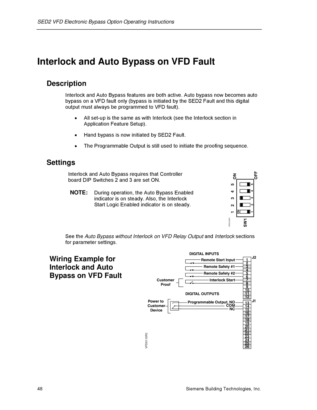
Interlock and Auto Bypass requires that Controller board DIP Switches 2 and 3 are set ON.
NOTE: During operation, the Auto Bypass Enabled indicator is on steady. Also, the Interlock Start Logic Enabled indicator is on steady.
ON
1 2 3 4 5
VFD0120R1
|
|
|
| 5 | |
|
|
|
|
|
|
| 4 | |
|
|
|
|
|
|
|
| 3 |
|
|
|
|
| 2 |
|
| |
ON |
|
|
|
| |
1 | ||
|
|
|
| SW1 | |
OFF
See the Auto Bypass without Interlock on VFD Relay Output and Interlock sections for parameter settings.
Wiring Example for Interlock and Auto Bypass on VFD Fault
Customer
Proof
DIGITAL INPUTS |
Remote Start Input |
Remote Safety #1 |
Remote Safety #2 |
Interlock Start |
1
2
3
4
5
6
7
8
9
J2
Power to Customer Device
VFD0115R2
DIGITAL OUTPUTS
Programmable Output, NO COM NC
10
11
12
13J1
48 | Siemens Building Technologies, Inc. |