SED2 VFD Electronic Bypass Option Operating Instructions
Application Feature Setup
Overview
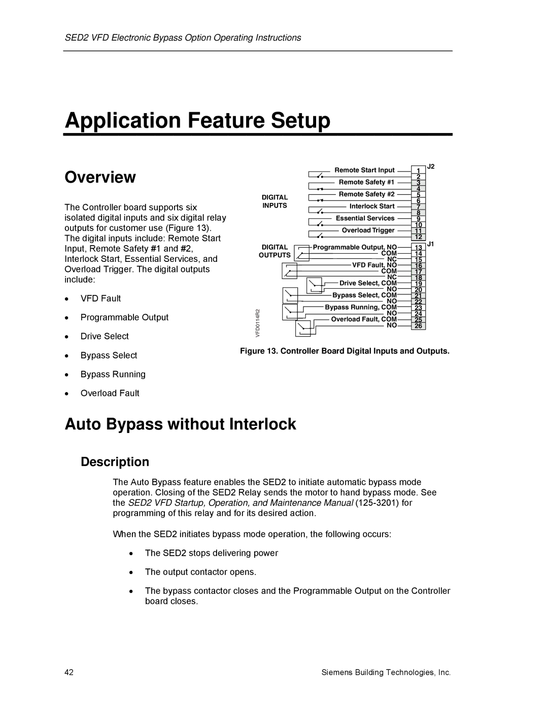
The Controller board supports six isolated digital inputs and six digital relay outputs for customer use (Figure 13). The digital inputs include: Remote Start Input, Remote Safety #1 and #2, Interlock Start, Essential Services, and Overload Trigger. The digital outputs include:
•VFD Fault
•Programmable Output
•Drive Select
•Bypass Select
•Bypass Running
•Overload Fault
| Remote Start Input | 1 | J2 |
|
| ||
| Remote Safety #1 | 2 |
|
| 3 |
| |
| Remote Safety #2 | 4 |
|
DIGITAL | 5 |
| |
| 6 |
| |
INPUTS | Interlock Start |
| |
7 |
| ||
| Essential Services | 8 |
|
| 9 |
| |
| Overload Trigger | 10 |
|
| 11 |
| |
|
| 12 |
|
DIGITAL | Programmable Output, NO | 13 | J1 |
OUTPUTS | COM | 14 |
|
| NC | 15 |
|
| VFD Fault, NO | 16 |
|
| COM | 17 |
|
| NC | 18 |
|
| Drive Select, COM | 19 |
|
| NO | 20 |
|
| Bypass Select, COM | 21 |
|
| NO | 22 |
|
VFD0114R2 | Bypass Running, COM | 23 |
|
NO | 24 |
| |
| Overload Fault, COM | 25 |
|
| NO | 26 |
|
Figure 13. Controller Board Digital Inputs and Outputs.
Auto Bypass without Interlock
Description
The Auto Bypass feature enables the SED2 to initiate automatic bypass mode operation. Closing of the SED2 Relay sends the motor to hand bypass mode. See the SED2 VFD Startup, Operation, and Maintenance Manual
When the SED2 initiates bypass mode operation, the following occurs:
•The SED2 stops delivering power
•The output contactor opens.
•The bypass contactor closes and the Programmable Output on the Controller board closes.
42 | Siemens Building Technologies, Inc. |