GPIO
LED
GPIO_10
D3 green
RS-232 Cable
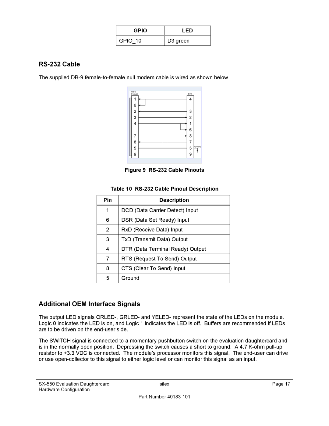
The supplied
Figure 9 RS-232 Cable Pinouts
Table 10 RS-232 Cable Pinout Description
Pin | Description |
|
|
1 | DCD (Data Carrier Detect) Input |
|
|
6 | DSR (Data Set Ready) Input |
|
|
2 | RxD (Receive Data) Input |
|
|
3 | TxD (Transmit Data) Output |
|
|
4 | DTR (Data Terminal Ready) Output |
|
|
7 | RTS (Request To Send) Output |
|
|
8 | CTS (Clear To Send) Input |
|
|
5 | Ground |
|
|
Additional OEM Interface Signals
The output LED signals
The SWITCH signal is connected to a momentary pushbutton switch on the evaluation daughtercard and is in the normally open position. Depressing the switch causes a short to ground. A 4.7
silex | Page 17 | |
Hardware Configuration |
|
|
| Part Number |
|