Serial Ports
The two serial ports can be accessed with
The two logical serial port headers are located at JP2 and JP6. The serial ports provide four dedicated signals and three optional signals. The optional signals are configured using jumpers. Table 5 details the serial port signal descriptions.
Table 5 Logical Serial Port Signal Descriptions
Pin | Signal | Input/Output | Pin | Signal | Input/Output |
|
|
|
|
|
|
1 | DCD | Input | 2 | DSR | Input |
|
| Enabled via header |
|
| Enabled via header |
|
|
|
|
|
|
3 | RXD | Input | 4 | RTS | Output |
|
|
|
|
|
|
5 | TXD | Output | 6 | CTS | Input |
|
|
|
|
|
|
7 | DTR | Output | 8 | No |
|
|
| Enabled via header |
| Connect |
|
|
|
|
|
| |
|
|
|
|
|
|
9 | GND |
| 10 | 3.3V |
|
|
|
|
|
|
|
All signals are 0 to 3.3 V logic signals.
To use header JP2, disable the
Using the Optional Serial Signals
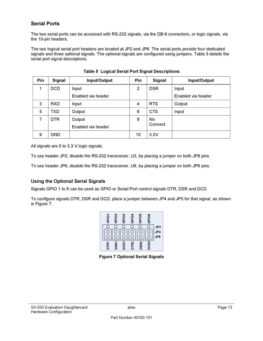
Signals GPIO 1 to 6 can be used as GPIO or Serial Port control signals DTR, DSR and DCD.
To configure signals DTR, DSR and DCD, place a jumper between JP4 and JP5 for that signal, as shown in Figure 7.
GPIO1 | GPIO2 | GPIO3 | GPIO4 | GPIO5 | GPIO6 |
|
|
|
|
| JP3 |
|
|
|
|
| JP4 |
|
|
|
|
| JP5 |
DTR1 | DSR1 | DCD1 | DTR2 | DSR2 | DCD2 |
Figure 7 Optional Serial Signals
silex | Page 13 | |
Hardware Configuration |
|
|
| Part Number |
|